Eureka AIR delivers breakthrough ideas for toughest innovation challenges, trusted by R&D personnel around the world.

Aluminum-steel heat release welding method

An exothermic welding and aluminum block technology, applied in the direction of aluminothermic welding equipment, welding equipment, welding medium, etc., can solve the problems of aluminum-steel welding joint performance degradation, uncontrolled cost, low economic efficiency, etc., and achieve easy access , Simple structure, stable reaction process

Inactive Publication Date: 2014-03-19
WUHAN UNIV
View PDF13 Cites 10 Cited by
  • Summary
  • Abstract
  • Description
  • Claims
  • Application Information

AI Technical Summary

Problems solved by technology

Due to the very different thermophysical properties of aluminum and steel, the solid solubility is low, and intermetallic compounds are easily formed while forming alloys, which leads to the performance degradation of aluminum-steel welded joints, and whether the formed welded joints are mechanically bonded or There is no strong experimental explanation on the issue of metallurgical bonding
Therefore, in order to improve the strength of the aluminum-steel welding street, the welding process must be improved. The practice of pre-preparing a layer of aluminum on the steel surface in patent 200910072270.2 does reduce the generation of interfacial compounds and improve the quality of welding to a certain extent, but The welding method of this method uses MIG welding, which does not control the cost
In patent 201310367501.9, a layer of aluminum is covered on the surface of steel by hot-dip aluminum to realize the metallurgical bonding of aluminum-steel self-propagating welding, but the formula used in this method contains SnO 2 and Cu 2 The economy of O is not high, and the cost is not controlled

Method used


Image

  • Aluminum-steel heat release welding method
  • Aluminum-steel heat release welding method
  • Aluminum-steel heat release welding method

Examples


Embodiment 1

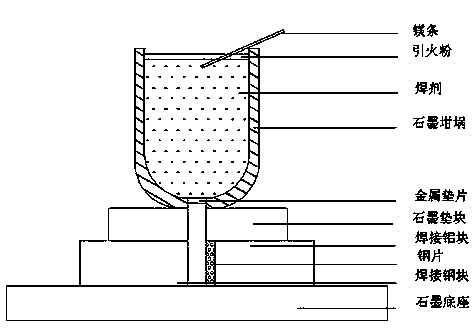
[0029] Grind the sections of the aluminum block and steel block to be welded with the same cross-sectional area, and place a pre-polished steel sheet of moderate size between the aluminum block and the steel block to be welded. The cross-sectional shape of the steel sheet is an inverted triangle , with a thickness of 3 mm; the aluminum block and the steel block according to figure 1 As shown, it is placed under the graphite crucible, and the center of the gap is aligned with the through hole at the bottom of the graphite crucible; there is a graphite base under the aluminum block and steel block, and there is a graphite pad with a through hole between the aluminum block, steel block and the graphite crucible. The through hole at the bottom of the graphite crucible is blocked by a metal sheet. The mass percentages were 22% of Al powder (fineness of 200 mesh), 68% of Fe 2 o 3 powder, 7% Si powder and 3% CaF 2 Put the powder in a powder mixer, mix evenly to form flux, then pu...

Embodiment 2

[0031] Grind the sections of the aluminum block and steel block to be welded with the same cross-sectional area, and place a pre-polished steel sheet of moderate size between the aluminum block and the steel block to be welded. The cross-sectional shape of the steel sheet is an inverted triangle , with a thickness of 3 mm; the aluminum block and the steel block according to figure 1 As shown, it is placed under the graphite crucible, and the center of the gap is aligned with the through hole at the bottom of the graphite crucible; there is a graphite base under the aluminum block and steel block, and there is a graphite pad with a through hole between the aluminum block, steel block and the graphite crucible. The through hole at the bottom of the graphite crucible is blocked by a metal sheet. The mass percentages were 24% of Al powder (fineness of 200 mesh), 66% of Fe 2 o 3 Powder, 6% Si powder and 4% NaF powder are placed in a powder mixer, mixed evenly to form flux, then t...

Embodiment 3

[0033]Grind the sections of the aluminum block and steel block to be welded with the same cross-sectional area, and place a pre-polished steel sheet of moderate size between the aluminum block and the steel block to be welded. The cross-sectional shape of the steel sheet is an inverted triangle , with a thickness of 3 mm; the aluminum block and the steel block according to figure 1 As shown, it is placed under the graphite crucible, and the center of the gap is aligned with the through hole at the bottom of the graphite crucible; there is a graphite base under the aluminum block and steel block, and there is a graphite pad with a through hole between the aluminum block, steel block and the graphite crucible. The through hole at the bottom of the graphite crucible is blocked by a metal sheet. The mass percentages were 26% of Al powder (fineness of 200 mesh), 64% of Fe 2 o 3 powder, 5% Si powder and 5% KF powder in a powder mixer, mix evenly to form flux, then put the flux int...


PUM

PropertyMeasurementUnit
thicknessaaaaaaaaaa

Abstract

The invention discloses an aluminum-steel heat release welding method. The method comprises the steps that to-be-welded sections of an aluminum block and a steel block are polished cleanly; a pre-polished steel sheet is placed to cling to the aluminum block between a gap of the to-be-welded sections of the aluminum block and the steel block; a bottom through hole of a graphite crucible is aligned to the center of the gap; a self-propagating welding flux is put into the graphite crucible; pyrophoric powder on the surface of the self-propagating welding flux is ignited; molten liquid generated by self-propagating welding flux reaction flows into the gap between the aluminum block and the steel block from the bottom small hole of the graphite crucible; the steel sheet is heated, molten, and cooled to a room temperature; and then aluminum-steel welding is accomplished. The adopted self-propagating welding flux comprises the following raw materials by mass percent: 22-28% of Al powder, 62-68% of Fe2O3 powder, 4-7% of Si powder and 3-6% of slag forming constituent. The method is simple to operate, simple in equipment, stable, safe and reliable in reaction, extensive in raw material, low in cost and less in joint slag inclusion, and has a great industrial popularization value; aluminum steel bonding adopts metallurgical bonding; and the quality is good.

Description

[0001] technical field [0002] The invention belongs to the technical field of material processing and manufacturing, and in particular relates to an aluminum-steel exothermic welding method. Background technique [0003] As a silver-white light metal, aluminum has excellent ductility and is also the most abundant metal element in the earth's crust, so it has important development prospects in the fields of aviation, construction, and automobiles. Due to its low price and reliable performance, steel has become one of the most used materials and is an indispensable component in construction, manufacturing and people's lives. Combining the excellent properties and application prospects of aluminum and steel, welding between aluminum and steel dissimilar materials has naturally become a hot spot. However, due to the very different properties of aluminum and steel, the melting point is very different, so it faces great technical challenges in actual welding. [0004] At prese...

Claims


Application Information

Patent Timeline
Patent Type & Authority Applications(China)
IPC IPC(8): B23K23/00B23K35/362
CPCB23K23/00B23K35/361B23K2103/18
Inventor 张国栋邱智华张晖
Owner WUHAN UNIV
Why Eureka
Eureka Blog
Learn More