Method and device for adjusting optical axis parallelism of transmitting and a receiving optical system of dual-axis laser ceilometer

An optical system and optical axis parallel technology, applied in the direction of measuring devices, radio wave measuring systems, instruments, etc., can solve the problems of time-consuming adjustment process, complicated installation and adjustment, unsuitable for quick adjustment, etc., to achieve simple structure, easy and fast operation Effect

Active Publication Date: 2014-03-19
皖江新兴产业技术发展中心
View PDF12 Cites 6 Cited by
  • Summary
  • Abstract
  • Description
  • Claims
  • Application Information

AI Technical Summary

Problems solved by technology

[0004] The commonly used adjustment method is to observe the strength of the echo signal, but because the optical axis offset is generally relatively large under the initial assembly conditions of the transceiver optical system, it is difficult to quickly adjust to a suitable position, so the adjustment process is very time-consuming; another type of adjustment The method is to use an optical device to return the emitted laser light to the receiving system in a parallel direction, add a spectroscopic device and a CCD monitoring device to the receiving optical system, and observe the beam imaging. The installation and adjustment of these devices are more complicated, and the structure of the receiving optical system There are certain changes, so it is not suitable for quick adjustment

Method used


Image

  • Method and device for adjusting optical axis parallelism of transmitting and a receiving optical system of dual-axis laser ceilometer
  • Method and device for adjusting optical axis parallelism of transmitting and a receiving optical system of dual-axis laser ceilometer
  • Method and device for adjusting optical axis parallelism of transmitting and a receiving optical system of dual-axis laser ceilometer

Examples


Embodiment Construction

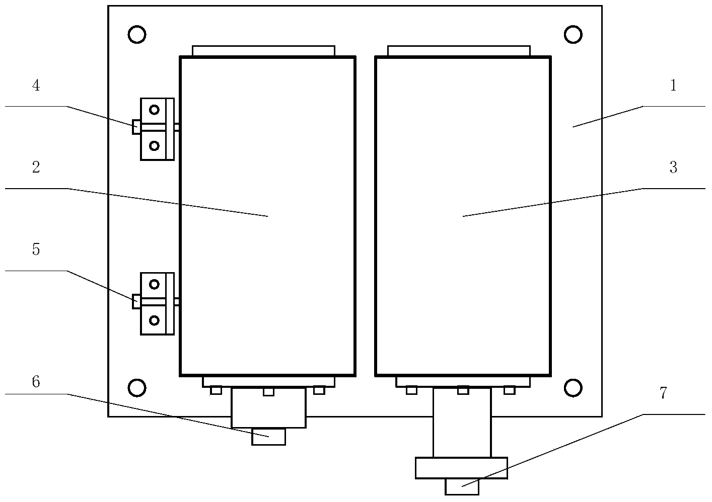
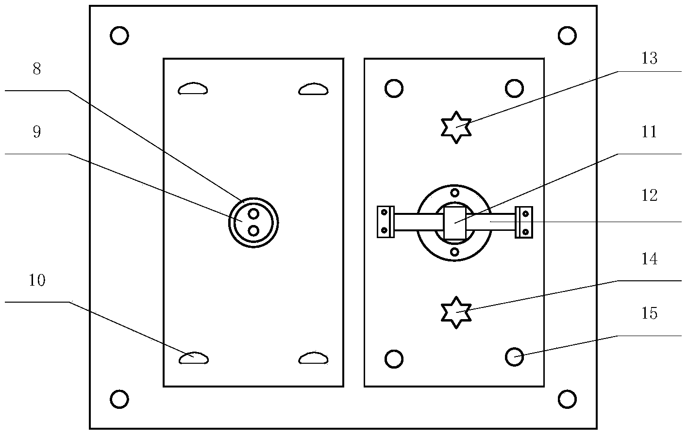
[0016] The structure of the optical axis parallel adjustment device for the transceiver optical system of the dual-axis laser ceilometer is as follows: figure 1 , 2 As shown, there are mainly flat plate 1, transmitting telescope 2, receiving telescope 3, horizontal adjustment structures 4, 5, 8, 9, 10, pitch adjustment structures 11, 12, 13, 14, 15, transmitting CCD detection module 6, receiving CCD The detection module 7 is composed of a visible light source and a computer. The flat plate 1 is fixed on the cloud platform with adjustable horizontal and pitch directions. The transmitting telescope 2 and the receiving telescope 3 are fixed on the flat plate 1 by locking screws 10 and 15 respectively. In the flange 8 on the flat plate 1, the horizontal direction adjustment of the transmitting telescope is realized by adjusting the screws 4 and 5; the bottom center of the receiving telescope is connected with a sleeve 11, and the pin 12 fixed on the flat plate 1 passes through th...


PUM


Abstract

The invention discloses a method and a device for adjusting the optical axis parallelism of a transmitting and receiving optical system of a dual-axis laser ceilometer. The method is characterized in that a transmitting telescope and a receiving telescope are fixed on the same plate, the transmitting telescope can be adjusted in the horizontal direction, the receiving telescope can be adjusted in the pitching direction, a CCD detection module is installed at the position of the transmitting telescope, another CCD detection module is installed at the position of the receiving telescope, a visible light source target is placed in an area where an overlap factor is 1 in front of a transmitting and receiving optical path, view field images detected by the two CCD detection modules are inputted to a computer, the position of the target in the view field image is determined, a view field image of the transmitting and receiving optical path is observed on the computer, and the target is enabled to be imaged in the two view fields clearly and located at the center of the view fields, thereby completing once transmitting and receiving optical path adjustment; and then a further target is selected. The method and the device disclosed by the invention are applied to adjustment and calibration of the transmitting and receiving optical path of the laser ceilometer, simple in structure, and simple and quick in operation.

Description

technical field [0001] The invention relates to the adjustment of the optical path of a dual-axis laser ceilometer, in particular to a method and a device for parallel adjustment of the optical axes of a transceiver optical system of a dual-axis laser ceilometer. Background technique [0002] The laser ceilometer is an active atmospheric remote sensing device that uses laser technology to measure cloud information. The measurement principle is: the laser emits a high-frequency narrow laser pulse, which passes through the atmosphere, aerosol and cloud vertically after being collimated by the emission optical system; The ceilometer receiving optical system receives the backscatter echo signal, and the signal is collected by AD and then inverted by the computer. Based on the radar equation, the backscatter profile is obtained by inversion, and the cloud base and cloud height are obtained through the cloud layer identification algorithm. information. The semiconductor laser cei...

Claims


Application Information

Patent Timeline
Patent Type & Authority Applications(China)
IPC IPC(8): G05D3/12G01S7/481G01S17/08
Inventor 李胜高闽光张玉钧王锋平金岭尤坤王康徐金凤刘文清
Owner 皖江新兴产业技术发展中心
Why Eureka
Try Eureka