Method for preparing nitride ceramic coating applied to lithium ion battery

A technology of nitride ceramics and lithium-ion batteries, applied in coatings, battery electrodes, battery components, etc., to achieve good thermal barrier, improve liquid absorption and liquid retention capabilities, improve hydrofluoric acid resistance and thermal shock resistance Effect

Inactive Publication Date: 2014-03-19
HEFEI GUOXUAN HIGH TECH POWER ENERGY
View PDF5 Cites 52 Cited by
  • Summary
  • Abstract
  • Description
  • Claims
  • Application Information

AI Technical Summary

Problems solved by technology

The prior art has mastered the preparation of oxide ceramic slurry and coating on the surface of

Method used


Image

  • Method for preparing nitride ceramic coating applied to lithium ion battery
  • Method for preparing nitride ceramic coating applied to lithium ion battery
  • Method for preparing nitride ceramic coating applied to lithium ion battery

Examples


Example Embodiment

[0030] Example 1 (take oil-based slurry as an example)

[0031] A nitride ceramic coating applied to lithium-ion batteries, consisting of the following components by weight percentage:

[0032]

[0033]

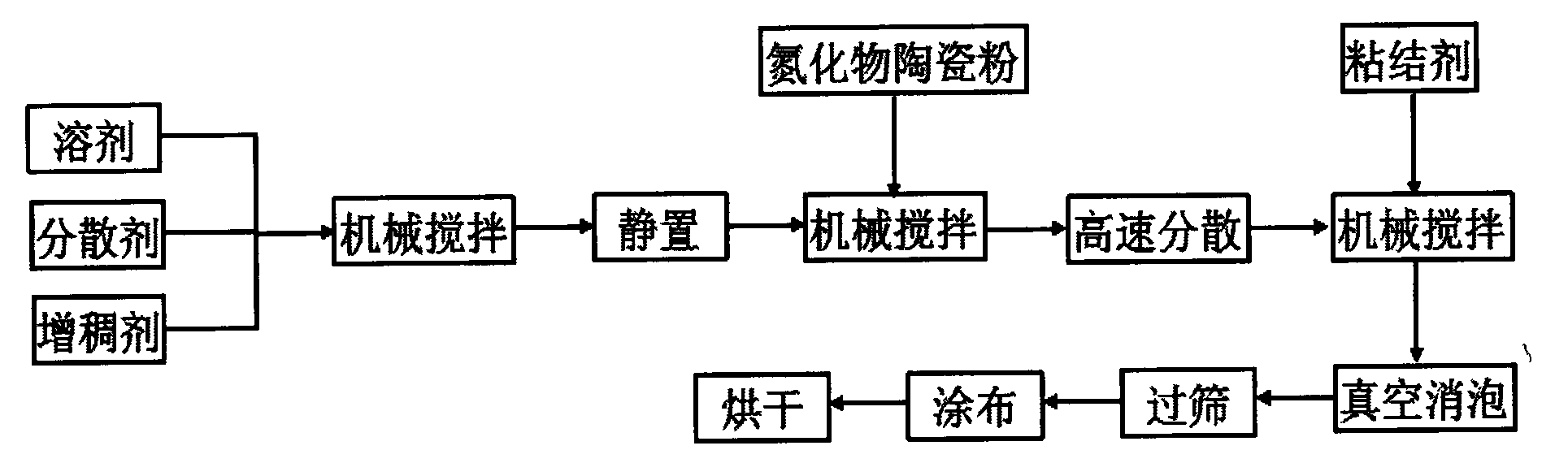
[0034] And prepared by the following steps:

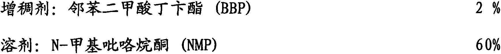
[0035] (1) Combine N-methylpyrrolidone (NMP), O-(2-aminopropyl)-O'-(2-methoxyethyl) polypropylene glycol (AMPG) and butyl phthalate (BBP) ) Mix and stir evenly according to the proportion, let stand for defoaming under vacuum conditions, and then add silicon nitride ceramic particles (Si 3 N 4 ), stir well and set aside;

[0036] (2) Transfer the above-prepared slurry to a vertical shear type micro-dispersing machine for high-speed dispersion. The speed is greater than 6000 rpm, and the current is controlled within 10A. The slurry is passed through the disperser at high speed 4 times to make The agglomerates in the slurry are completely dispersed, and then the binder polyvinylidene fluoride (PVDF) is added in proportion, and it is evenly...

Example Embodiment

[0038] Example 2 (take water-based slurry as an example)

[0039] A nitride ceramic coating applied to lithium-ion batteries, consisting of the following components by weight percentage:

[0040]

[0041] And prepared by the following steps:

[0042] (1) Combine deionized water, sodium carboxymethyl cellulose (CMC) and sodium silicate (NaSiO 3 ) Mix and stir evenly according to the proportion, let stand for defoaming under vacuum conditions, and then add silicon nitride ceramic particles (Si 3 N 4 ), stir well and set aside;

[0043] (2) Transfer the above-prepared slurry to a vertical shear type micro-dispersing machine for high-speed dispersion. The speed is greater than 6000 rpm, and the current is controlled within 10A. The slurry is passed through the disperser at high speed 4 times to make The agglomerates in the slurry are completely dispersed, and then the binder styrene-butadiene rubber (SBR) is added in proportion, and it is evenly dispersed by mechanical stirring, such as f...


PUM


Abstract

The invention discloses a nitride ceramic coating applied to a lithium ion battery. The nitride ceramic coating consists of the following components in parts by weight: 2-10 parts of adhesive, 10-40 parts of nitride ceramic particles, 0.5-3 parts of thickening agent, 0.05-2 percent of dispersing agent and the balance of solvent. The nitride ceramic coating is prepared by the following steps: (1) preparing slurry, namely uniformly mixing and stirring the solvent, the dispersing agent and the thickening agent, standing, defoaming, adding the nitride ceramic particles, uniformly dispersing and forming slurry A; (2) dispersing at high speed, namely dispersing the slurry A at high speed, then adding the additive, uniformly stirring, performing vacuum defoaming, and screening to form slurry B; (3) coating, namely coating the slurry B on an edge of the anode and/or the surface of the cathode and/or a diaphragm in the lithium ion battery, and drying at the temperature of 60-120 DEG C. According to the nitride ceramic coating, the liquid absorption capacity and liquid retaining capacity of the diaphragm or the pole piece can be effectively improved, the hydrofluoric acid resistance and thermal shock resistance of the pole piece or the diaphragm are improved, and a better heat barrier effect is achieved.

Description

Technical field [0001] The invention relates to a preparation method of a nitride ceramic coating applied to a lithium ion battery. Background technique [0002] Lithium-ion batteries have many advantages such as high voltage, long cycle life, high specific energy, low self-discharge, no memory effect, no pollution, and wide operating temperature range. Therefore, they have been widely used in mobile phones, notebooks, pure electric buses, Pure electric minibuses, pure electric cars, electric bicycles, military equipment, solar power stations, communication base stations and other fields. [0003] Generally speaking, lithium-ion batteries include five major components: positive electrode, negative electrode, separator, casing and electrolyte. Lithium-ion batteries provide electrical energy through the reversible chemical reaction of lithium insertion and lithium removal between the positive electrode and the negative electrode. The separator is located between the positive and ne...

Claims


Application Information

Patent Timeline
IPC IPC(8): H01M2/16H01M4/139C09D1/00H01M50/403H01M50/409H01M50/434
CPCY02E60/122H01M4/13H01M4/139C09D1/00H01M2004/021H01M50/403H01M50/431Y02E60/10
Inventor 张江伟刘成士宫璐王晨旭
Owner HEFEI GUOXUAN HIGH TECH POWER ENERGY
Why Eureka
Try Eureka