Multi-channel intelligent optical testing device

An optical test and multi-channel technology, applied in the field of communication, can solve the problems of low production efficiency, large size, high cost, etc., and achieve the effect of reducing test errors and ensuring accuracy

Active Publication Date: 2014-03-19
GUANGXUN SCI & TECH WUHAN
View PDF4 Cites 16 Cited by
  • Summary
  • Abstract
  • Description
  • Claims
  • Application Information

AI Technical Summary

Problems solved by technology

[0008] The technical purpose of the present invention is to overcome the problems existing in the prior art and provide a new type of multi-channel intelligent optical testing device. The device of the present invention can solve the problems of existing testing equipments with many types, high cost, low production efficiency and large size.

Method used


Image

  • Multi-channel intelligent optical testing device
  • Multi-channel intelligent optical testing device
  • Multi-channel intelligent optical testing device

Examples


Embodiment Construction

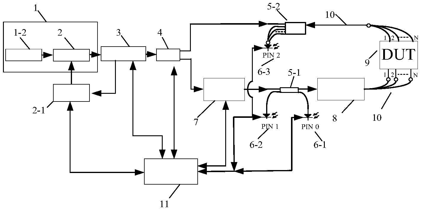
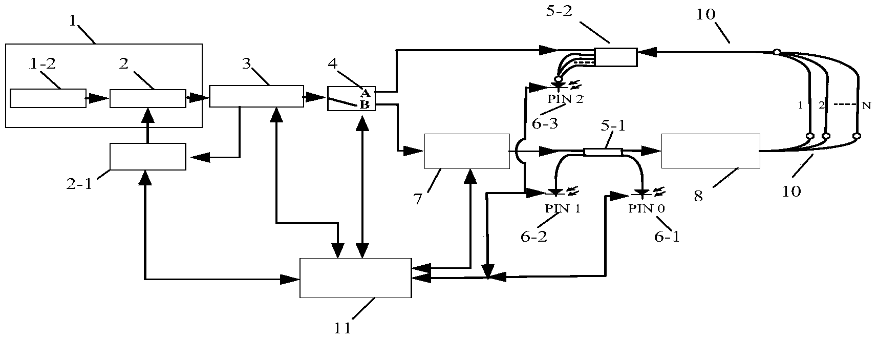
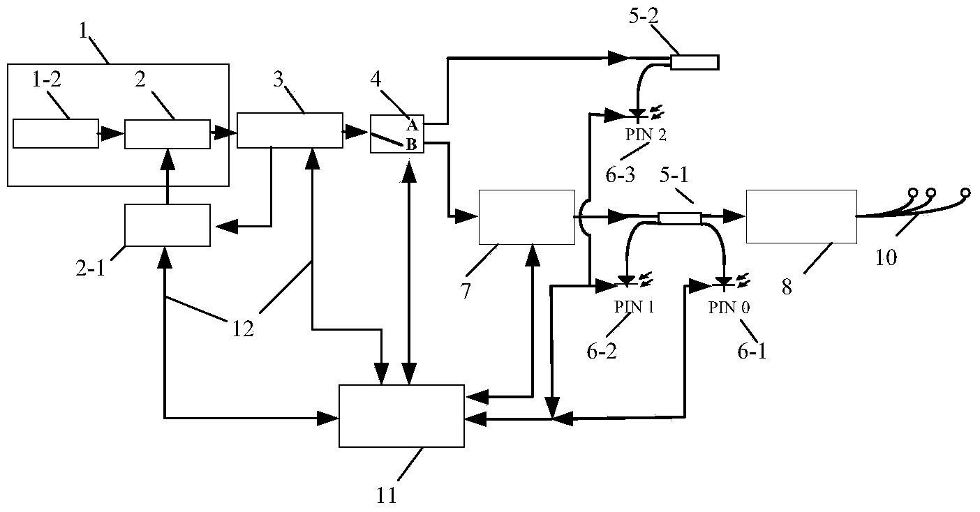
[0052] In order to make the purpose, technical solutions and advantages of this design clearer, this design will be further described in detail in conjunction with the drawings and embodiments.

[0053]The first embodiment of a multi-channel intelligent optical testing device of the present invention includes a broadband light source 1-2, an adjustable filter 2, a wavelength calibration monitoring module 3, an optical switch 4, a polarization controller 7, and a 1*N beam splitter 8. 2×2 splitter 5-1, N×N splitter 5-2, broadband light source 1-2 and adjustable filter 2 form light source 1, broadband light source 1-2 output terminal and adjustable filter 2 The output end of the tunable filter 2 is connected to the input end of the wavelength calibration monitoring module 3, the output end of the wavelength calibration monitoring module 3 is connected to the input end of the optical switch 4, and the output end of the optical switch 4 is connected to the polarization controller 7....


PUM


Abstract

The invention discloses a multi-channel intelligent optical testing device which comprises a light source, a light source control circuit, a wavelength calibration monitoring module and an optical switch which are sequentially connected. One output end of the optical switch is sequentially connected with a polarization controller, a 2*2 shunt and a 1*N optical splitter. One output end of the 2*2 shunt is connected with a first optical power detector, and one input end of the 2*2 shunt is connected with a second optical power detector. The other output end of the optical switch is connected with an N*N shunt, and output ends of the N*N shunt are connected with array optical power detectors in a one-to-one correspondence mode. The light source control circuit, the wavelength calibration monitoring module, the optical switch, the polarization controller, the first optical power detector, the second optical power detector and the array optical power detectors are connected with a control unit. The testing device can test optical indexes of a multi-channel module.

Description

[0001] technical field [0002] The invention relates to a testing device, in particular to a multi-channel intelligent testing device for optical index testing and verification of optical communication device modules, and the invention belongs to the communication field. [0003] Background technique [0004] In order to meet the demand for bandwidth and transmission rate, communication operators and system suppliers combine DWDM Dense Wavelength Division Multiplexing technology as the main means of current optical fiber communication. With the continuous upgrading of DWDM technology, optical fiber The wide use of communication networks makes the network topology more and more complex, and there are more and more devices and modules with different functions, such as dynamic channel equalizer (DGE Dynamic Gain Equaliztioner), adjustable power optical multiplexer (VMUX Variable Multiplexer) , Optical Add-Drop Multiplexer (OADM Optical Add-Drop Multiplexer), Attenuator (VOA v...

Claims


Application Information

Patent Timeline
Patent Type & Authority Applications(China)
IPC IPC(8): H04B10/07H04B10/25
Inventor 陈辉吴晓平孙莉萍郑勇志鲁佶王文刚陈义宗
Owner GUANGXUN SCI & TECH WUHAN
Why Eureka
Try Eureka