Magnetic material and coil component employing same

一种磁性材料、线圈的技术,应用在线圈零件领域,能够解决体积电阻率低等问题,达到高绝缘电阻、高磁导率、高机械强度的效果

Active Publication Date: 2014-03-19
TAIYO YUDEN KK
View PDF10 Cites 16 Cited by
  • Summary
  • Abstract
  • Description
  • Claims
  • Application Information

AI Technical Summary

Problems solved by technology

On the other hand, the volume resistivity of the material itself is significantly lower than conventional ferrites

Method used


Image

  • Magnetic material and coil component employing same
  • Magnetic material and coil component employing same
  • Magnetic material and coil component employing same

Examples


Embodiment 1~7

[0083] (raw material particles)

[0084] Using the composition of 4.5wt% Cr, 3.5wt% Si, and the rest Fe produced by the atomization method, in the particle size distribution, d50 is 10 μm, d10 is 4 μm, and d90 is 24 μm. Alloy powder is used as raw material particles. The aggregate surface of the alloy powder was analyzed by XPS to calculate the Fe Metal / (Fe Metal +Fe Oxide ), the result is 0.5.

[0085] (Manufacture of particle molded body)

[0086] 100 parts by weight of the raw material particles were stirred and mixed with 1.5 parts by weight of a PVA binder having a thermal decomposition temperature of 300° C., and 0.2 parts by weight of Zn stearic acid was added as a lubricant. Thereafter, molding was performed at the temperature and pressure disclosed in Table 1, and heat treatment was performed at 750° C. for 1 hour in an oxidizing environment with an oxygen concentration of 21%, thereby obtaining a particle molded body.

Embodiment 8

[0088] A commercially available alloy powder having a composition of Al5.5wt%, Si9.7wt%, and the remainder Fe, produced by an atomization method, and a particle size distribution of d50 of 10 μm, d10 of 3 μm, and d90 of 27 μm was used as raw material particles, A particle shaped body was obtained by the same treatment as in Example 1. However, as shown in Table 1, the temperature during forming before heat treatment and the pressure during forming were changed.

[0089] (evaluate)

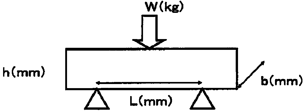
[0090] The apparent density, magnetic permeability, specific resistance, and three-point bending fracture strength of the obtained particle compacts were measured, respectively. image 3It is a schematic explanatory diagram of the measurement of the 3-point bending fracture stress. A load is applied to a measurement object (a plate-shaped particle compact with a length of 50 mm, a width of 10 mm, and a thickness of 4 mm) as shown in the figure, and the load W when the measurement object breaks i...

Embodiment 9

[0107] With the chemical composition identical with embodiment 1~7 and d50 is the alloy powder 15wt% of 5 μ m and has the chemical composition identical with embodiment 1~7 and d50 is the mixed powder of the alloy particle 85 wt % of 10 μ m as raw material particle, carries out With the same treatment as in Example 3, the apparent density obtained as a result is 6.27g / cm 3 particle shaped body. From the comparison between Example 3 and Example 9, it can be seen that by substituting a part of the raw material particles with particles with a smaller particle size, a particle molded body with a higher apparent density can be obtained.

[0108] [explanation of the symbol]

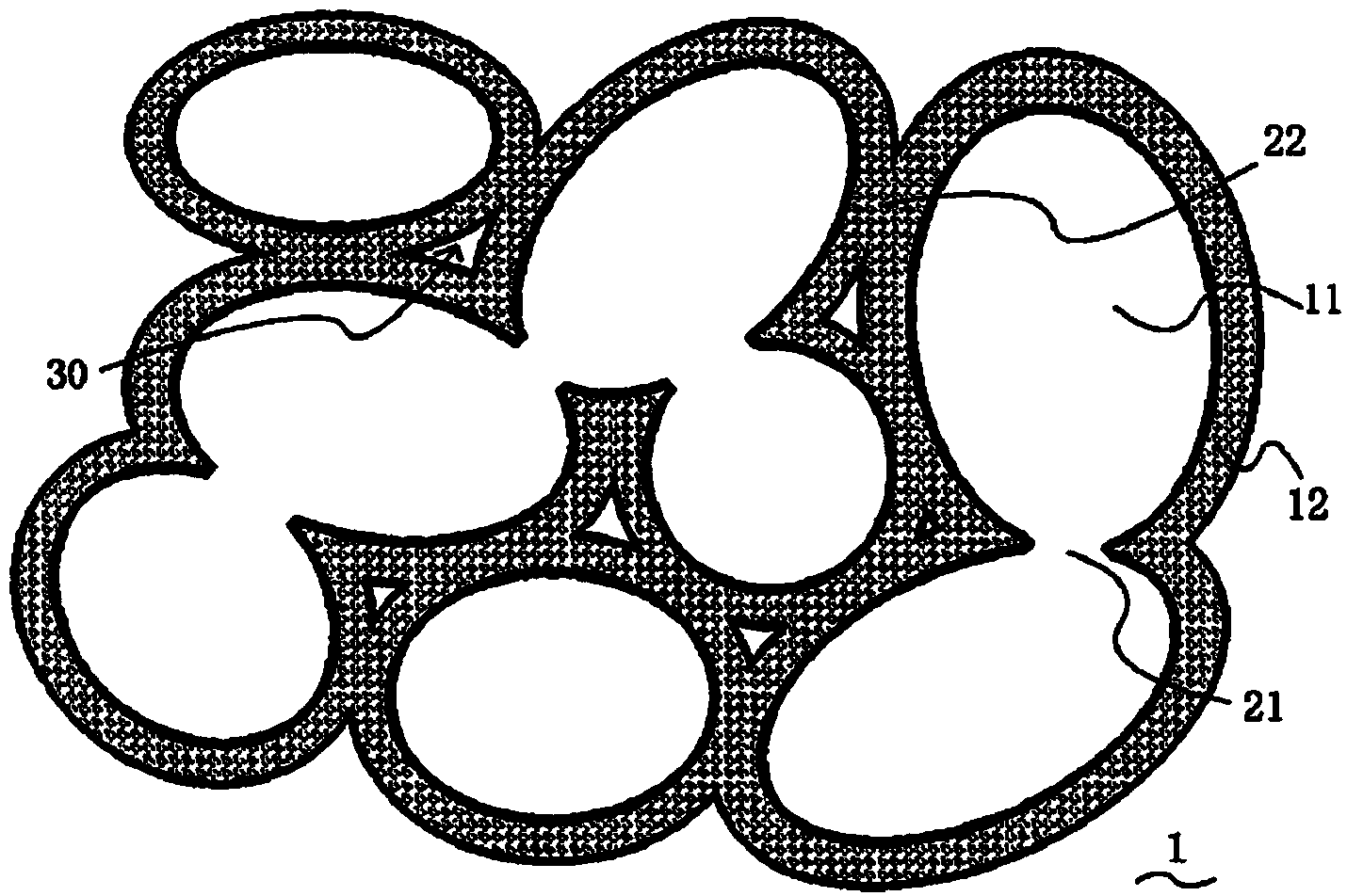
[0109] 1 particle shape

[0110] 11 metal particles

[0111] 12 Oxide coating

[0112] 21 Metals bonded to each other

[0113] 22 Combination of oxide films

[0114] 30 void

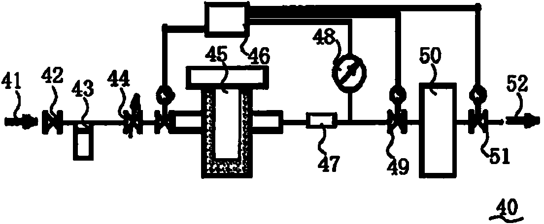
[0115] 40 Measuring device for molded body volume

[0116] 45 Sample room

[0117] 46 CPUs

[0118] 50 comparison room


PUM

PropertyMeasurementUnit
apparent densityaaaaaaaaaa

Abstract

The present invention addresses the problem of providing a new magnetic material with which further improvement in magnetic permeability is effected, and of providing a coil component employing such a magnetic material. According to the present invention, a magnetic material is provided wherein: a particle molding body (1) is provided in which a plurality of metallic particles (11) formed from an Fe-Si-M soft magnetic alloy (where M is a metallic element which oxidizes more readily than Fe) are molded; at least a portion of the periphery of each of the metallic particles (11) has oxide films (12) obtained by oxidizing the metallic particles (11); the particle molding body (1) is molded primarily through the bonding of the oxide films (12) which are formed on the peripheries of the respective adjacent metallic particles (11). The apparent density of the particle molding body (1) is 5.2g / cm3 or more, and is preferably 5.2-7.0g / cm3.

Description

technical field [0001] This case claims the priority of Japanese Patent Application No. 2011-149579 filed in Japan on July 5, 2011, the contents of which are incorporated herein by reference. [0002] The present invention relates to a magnetic material that can be used mainly as a core for coils, inductors, etc., and coil parts using the same. Background technique [0003] Coil components such as inductors, choke coils, and transformers (so-called inductance components) include a magnetic material and a coil formed inside or on the surface of the magnetic material. As a material of the magnetic material, ferrite such as Ni—Cu—Zn-based ferrite is generally used. [0004] In recent years, such coil parts have been required to increase the current (meaning higher rated current), and in order to meet this demand, studies have been made to replace the material of the magnetic body with an Fe-Cr-Si alloy from the conventional ferrite (see Patent Document 1). Fe-Cr-Si alloy or ...

Claims


Application Information

Patent Timeline
Patent Type & Authority Applications(China)
IPC IPC(8): H01F1/33B22F3/00B22F3/24C22C38/00H01F1/14H01F1/24H01F1/26B22F1/16
CPCB22F1/02H01F1/408H01F27/28H01F1/33C22C38/06B22F3/24H01F1/015H01F1/24H01F1/26C22C38/34B22F3/1007C22C38/02H01F1/14766B22F1/16H01F1/14
Inventor 小川秀树棚田淳
Owner TAIYO YUDEN KK
Why Eureka
Try Eureka