Flexible fiber spiral line demisting device

A flexible fiber and defogging device technology, which is applied to the separation of dispersed particles, chemical instruments and methods, separation methods, etc., can solve the problems of corrosion, large floor area, and low defogging efficiency, and achieve good water absorption and high efficiency. The effect of gas-liquid separation

Inactive Publication Date: 2014-03-26
JIANGHAN UNIVERSITY +2
View PDF7 Cites 18 Cited by
  • Summary
  • Abstract
  • Description
  • Claims
  • Application Information

AI Technical Summary

Problems solved by technology

[0011] To sum up, the main problems existing in the existing demister technology are: the defogging efficiency of the inertial demister and the centrifugal demister is low, the filter demister is easy to block, the cost of the electrostatic demister is high, and the floor area is large , Corrosion and fouling problems

Method used


Image

  • Flexible fiber spiral line demisting device
  • Flexible fiber spiral line demisting device

Examples


Embodiment 1

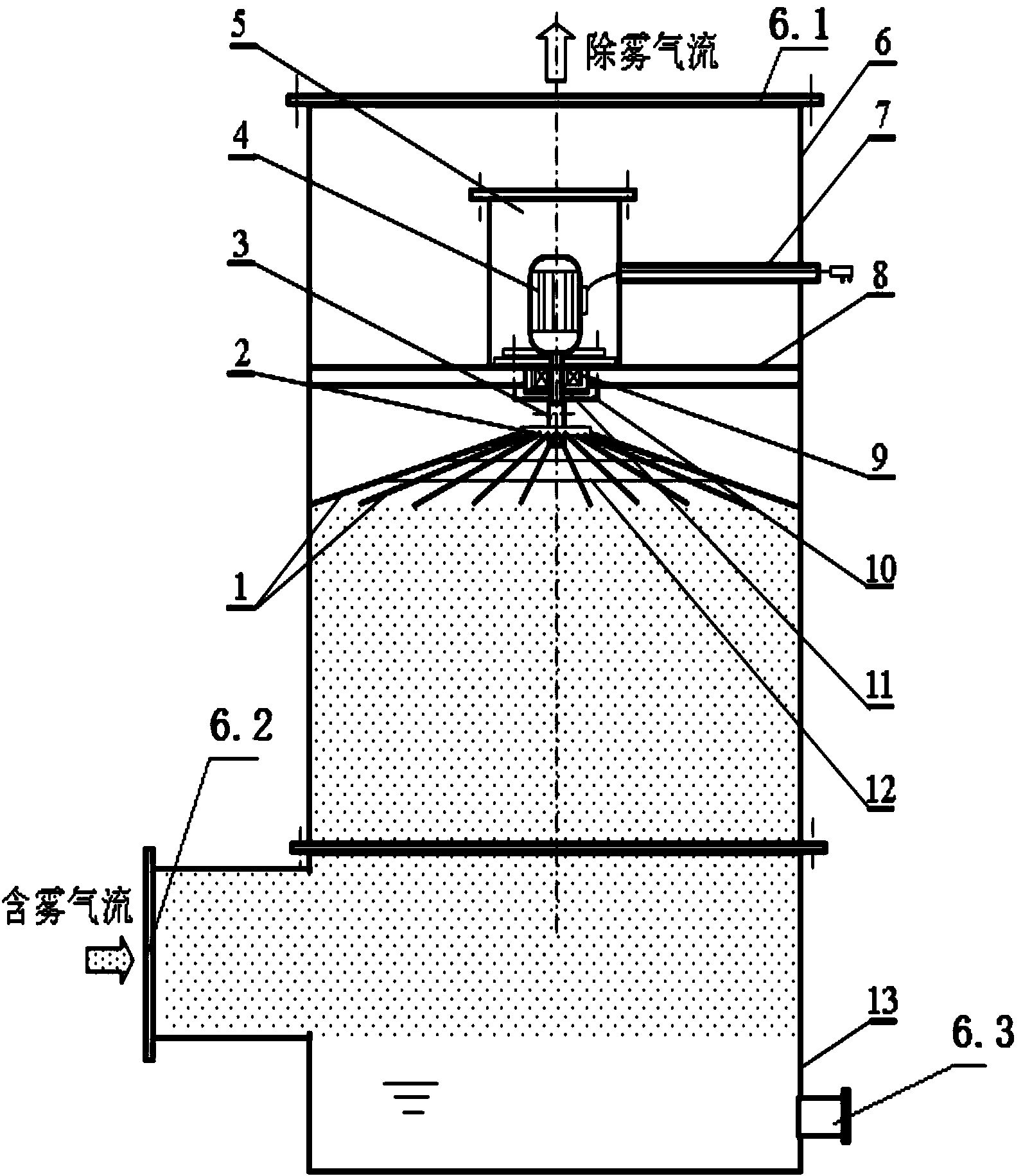
[0041] In embodiment 1, the flexible fiber spiral in the flexible fiber spiral defogging device installed on the vertical center line of the exhaust cylinder 6 is a single layer, and its structure is as follows: figure 1 Shown: including warp 1, disc 2, motor shaft sleeve 3, motor 4, sealing chamber 5, plastic conduit 7, support beam 8, bearing 9, sealing end cover 10, motor shaft 11 and weft 12.

[0042] Wherein, the top of the exhaust tube 6 is provided with an air outlet 6.1, the lower section is provided with an air inlet 6.2, and the bottom is provided with a water tank 13, and the water tank 13 communicates with the drain pipe 6.3, and the vertical center line of the upper section of the exhaust tube 6 is A motor 4 located in the sealed chamber 5 is provided, and the sealed chamber 5 passes through the cylinder wall of the exhaust cylinder 6 to communicate with the outside world through the conduit 7, so that the power supply wire of the motor 4 can pass through the condu...

Embodiment 2

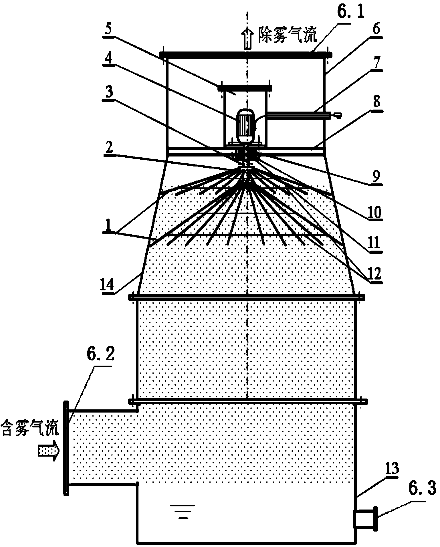
[0049] The number of layers of the flexible fiber spiral can be designed into multiple layers, but when it exceeds 5 layers, the pressure loss will increase significantly, and although the flexible fiber spiral is very light, if there are too many layers and it is a wet fiber thread, the weight will increase significantly . Therefore, the number of flexible fiber spirals is preferably 1-5 layers, and one layer of discs 2 is correspondingly installed with one layer of flexible fiber spirals.

[0050] In addition, when the exhaust cylinder 6 is a straight pipe, the warps in the multilayer flexible fiber spirals can have the same length; The increase or decrease of the cylinder diameter increases or shortens accordingly, and the control of its length is still "when the warp 1 rotates at a high speed, it is better for the free end to be in contact with the cylinder wall of the exhaust cylinder 6 or to be slightly longer",

[0051] In this example, if figure 2 As shown, the exha...


PUM

PropertyMeasurementUnit
diameteraaaaaaaaaa
diameteraaaaaaaaaa
diameteraaaaaaaaaa

Abstract

The invention relates to a flexible fiber spiral line demisting device, which solves the problems that the existing demising device has low demisting efficiency, the filter type demister is easy to block and the static demister is high in cost and large in occupied area and is corroded and scaled. According to the technical scheme, the flexible fiber spiral line demisting device comprises a gas inlet, a gas outlet and an exhaust cylinder of a liquid discharge pipe, wherein a motor is arranged on the vertical center line of the upper section of the exhaust cylinder; a rotating shaft of the motor is sleeved with a shaft sleeve; at least one layer of disc is arranged in the axis direction of the shaft sleeve; flexible fiber spiral lines are arranged on the disc; the flexible fiber spiral lines comprise a plurality of warps; one end of each warp is connected to the disc uniformly and the other end of each warp is a free end. The flexible fiber spiral line demisting device has the advantages of low resistance, high efficiency, no occupied area, no corrosion, no scaling and blockage, large flue gas treatment quantity, simple structure, light weight, low energy consumption and low cost.

Description

technical field [0001] The invention relates to a demisting device for mist-containing airflow, in particular to a flexible fiber spiral demisting device. Background technique [0002] The mist eliminator is the key equipment in the wet dust removal, flue gas desulfurization and denitrification system. Common demisters include inertial demisters, centrifugal demisters, filter demisters, and electrostatic demisters. [0003] The baffle plate demister is a typical inertial demister (Dong Yiren, Sun Fengzhen. Tower Equipment Defog Technology. Chemical Production and Technology. 2000, 7(2): 6-11). The tortuous flow between the droplets collides with the baffle and is trapped. The resistance of the baffle demister is low, but the demisting efficiency is very low, usually no more than 60%. [0004] Centrifugal demisters mainly include swirl plate demisters, cyclone demisters, and rotary demisters. [0005] The swirl plate demister is composed of several blades inclined at a ce...

Claims


Application Information

Patent Timeline
Patent Type & Authority Applications(China)
IPC IPC(8): B01D45/14
Inventor 石零向晓东吴高明莫亚平余新明汤静芳韩书勇常玉峰
Owner JIANGHAN UNIVERSITY
Why Eureka
Try Eureka