Industrial waste gas treatment system and treatment method

A technology for industrial waste gas and treatment methods, applied in separation methods, chemical instruments and methods, and separation of dispersed particles, which can solve problems such as increased equipment investment costs, unevenness, and secondary pollution, and achieve high filtration and adsorption efficiency and equipment structure Simple, no secondary pollution effect

Inactive Publication Date: 2015-12-02
杨凯翔 +2
View PDF8 Cites 0 Cited by
  • Summary
  • Abstract
  • Description
  • Claims
  • Application Information

AI Technical Summary

Problems solved by technology

[0007] Although the above-mentioned various methods play an important role in the current gas purification, these methods also have their insurmountable disadvantages: after a period of use, the efficiency of the electric capture method is reduced due to the accumulation of deposits, and the cleaning of deposits is also difficult. It is very troublesome, especially tar. It is not only difficult to clean up, but also the cleaned substances are not easy to handle, which will cause secondary pollution. When the electric trap loses its effect, the internal core part must be replaced, which will increase the investment cost of the equipment. The capture method has strict requirements on the temperature of the exhaust gas, and the scope of use is limited; the washing method not only needs to consume a large amount of water or other chemical solutions, but also needs to purify the used liquid, which is costly and easy to cause secondary pollution The currently used adsorption method mainly filters the exhaust gas containing particles or liquid droplets, and can also absorb a certain amount of odor, but its absorption rate for fine particles is not high. Due to the limitation of the structure of the adsorption equipment, the filter gas will be unstable, Inhomogeneous phenomenon, in addition, due to the limitation of cloth and ash removal, it has great limitations in use; the bag filter method is mainly used for ash removal, and it cannot be used for sticky substances and irritating smells. waste gas treatment
[0008] Due to the disadvantages of the above-mentioned various methods, the simple use of these methods can no longer meet the increasingly stringent purification requirements.

Method used


Image

  • Industrial waste gas treatment system and treatment method

Examples


Embodiment Construction

[0027] The present invention will be described in further detail below in conjunction with the accompanying drawings, but the protection scope of the present invention is not limited by the embodiments.

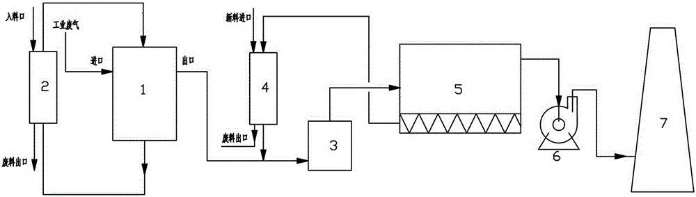
[0028] Such as figure 1 As shown, in the industrial waste gas treatment method of the present invention, the industrial waste gas first enters the adsorber provided with adsorption materials for adsorption and filtration, and the gas after being adsorbed and filtered passes through the gas outlet of the adsorber and enters the gas-powder mixer through the pipeline, and the sprayed powder Further mixing and adsorption, the mixed and adsorbed gas enters the bag filter through the pipeline for another filtration and adsorption, and the filtered and adsorbed gas is directly introduced into the chimney by the induced draft fan for discharge. Among them, the adsorption material filled in the adsorber is circulated and replaced by the circulating granular material supply and dischar...


PUM


Abstract

The invention discloses a waste gas treatment system, and in particular relates to an industrial waste gas treatment system and an industrial waste gas treatment method. The structure of the industrial waste gas treatment system is as follows: an industrial waste gas inlet is formed in an adsorber (1), a gas outlet of the adsorber (1) is communicated with a gas-powder mixer (3) through a pipeline, a gas outlet of the gas-powder mixer (3) is connected with a cloth bag dust collector (5) with an induced draft fan (6) through a pipeline, and a gas outlet of the cloth bag dust collector (5) is communicated with a chimney (7) through a pipeline via the induced draft fan (6). Compared with an existing common purification system, the industrial waste gas treatment system and the industrial waste gas treatment method have the characteristics of simple process, low energy consumption and low investment, and significant progress in the purification effect, production cost and investment compared with the prior art.

Description

technical field [0001] The invention relates to a waste gas treatment system, in particular to an industrial waste gas treatment system and a treatment method. Background technique [0002] At present, in solving the problem of environmental pollution caused by industrial waste gas, the following methods are basically used for treatment: [0003] Electric capture method: it uses high-voltage static electricity to capture harmful particles or tar in the exhaust gas; [0004] Washing method: use water or other liquids to absorb or dissolve harmful components in the exhaust gas; [0005] Adsorption method: it uses porous solid media or chemical agents to accumulate or condense one or more components in the gas on the surface to achieve the purpose of separation; [0006] Filtration method: mainly through the bag to collect the dust in the exhaust gas. [0007] Although the above-mentioned various methods play an important role in the current gas purification, these methods a...

Claims


Application Information

Patent Timeline
Patent Type & Authority Patents(China)
IPC IPC(8): B01D53/02
Inventor 杨凯翔任春雷杨懿
Owner 杨凯翔
Why Eureka
Try Eureka