
fully-automatic regulating SNCR (selective non-catalytic reduction) denitrification device

A fully automatic, denitrification technology, applied in the field of SNCR denitrification devices, can solve the problems of inability to achieve denitrification effect, limited boiler space, uneven distribution of ammonia, etc., and achieve the effect of simplifying the scope of equipment, simple construction and optimizing process flow

Inactive Publication Date: 2014-03-26
广东清华中邦热能科技有限公司
View PDF5 Cites 14 Cited by
  • Summary
  • Abstract
  • Description
  • Claims
  • Application Information

AI Technical Summary

Problems solved by technology

[0011] The traditional SNCR technology is prone to the problem of uneven distribution of ammonia due to the limited boiler space. Generally, each injector is controlled by a urea solution flow regulating valve. However, when the actual operating conditions are inconsistent with the commissioning conditions, In some cases, this relatively fixed flow control method will cause the urea solution and NO in the area of ​​the SNCR device to X The reaction is inconsistent, and the ideal denitrification effect cannot be achieved

Method used


Image

  • fully-automatic regulating SNCR (selective non-catalytic reduction) denitrification device
  • fully-automatic regulating SNCR (selective non-catalytic reduction) denitrification device
  • fully-automatic regulating SNCR (selective non-catalytic reduction) denitrification device

Examples


Embodiment Construction

[0032] The present invention will be described in further detail below in conjunction with the accompanying drawings.

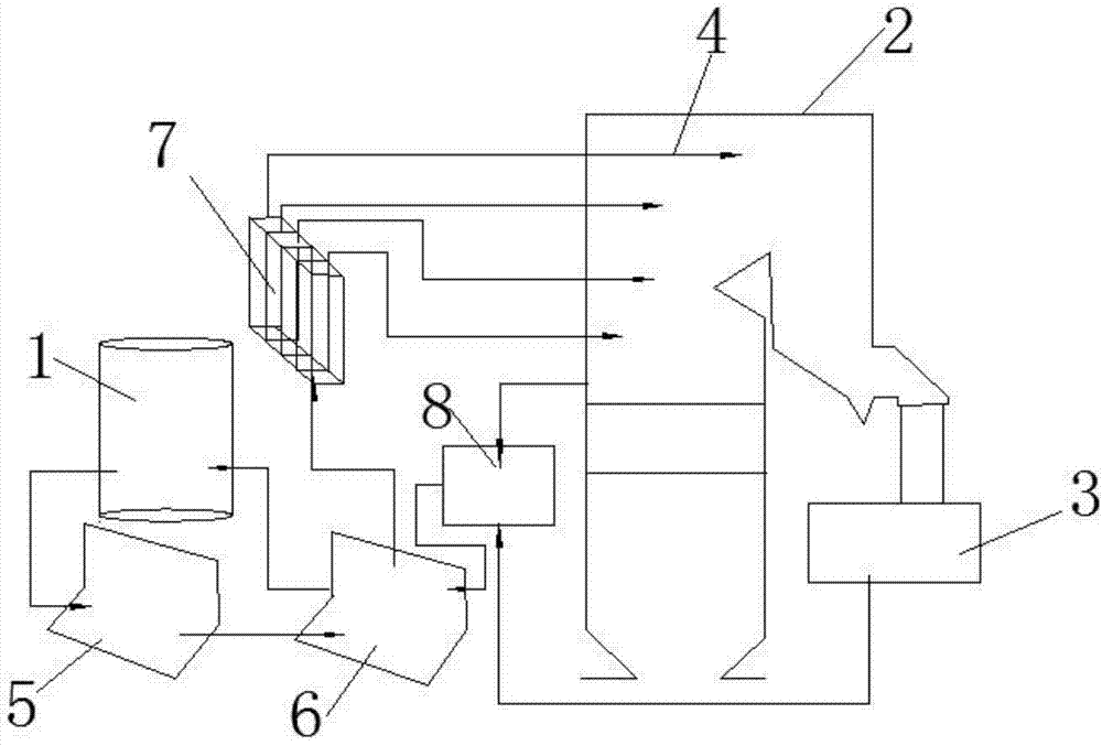
[0033] Such as figure 1 As shown, the present invention is a CFD-based SNCR denitrification device for industrial boilers, including a urea preparation and storage module 1, a boiler 2, a catalytic reaction device 3, and a CFD simulation calculation based on a boiler furnace wall injection module 4, and a delivery cycle module. 5. The metering dilution module 6, the distributing injection module 7, and the control module 8.

[0034] The specific process is that the control module 8 X The content, real-time characteristics of the individual boilers are calculated, and the calculated required urea solution is prepared and stored in the module 1. Under the specific adjustment of the circulation module 5, it is quantitatively diluted by the metering dilution module 6 and then distributed to the injection module 9. The distribution injection module 7 is directly...


PUM


Abstract

The invention relates to a flue gas denitrification device, and particularly relates to a fully-automatic regulating SNCR (selective non-catalytic reduction) denitrification device. The SNCR denitrification device is optimized further based on an original SNCR denitrification technique. The SNCR denitrification device for the fully-automatic regulating comprises a reducing agent (urea solution) preparation and storage module, a conveying and circulation module, an on-line metering and diluting module, and a distributing and jetting module arranged on the boiler wall based on CFD (computational fluid dynamics) simulation computation. The SNCR denitrification device for the fully-automatic regulating is characterized in that particle urea is conveyed to the storage module after being prepared into a urea solution; the conveying and circulation module and the metering and diluting module are arranged between a urea storage tank and the jetting module; the urea solution is quantitatively distributed in the jetting module after being metered and diluted, and a jet gun in the module is used for jetting; the storage module, the conveying and circulation module, the metering and diluting module, and the distributing and jetting module are controlled by a control module. According to the device, based on conventional SNCR, the technological process is optimized; an ammonia nitrogen reaction region at the rear end is controlled accurately; meanwhile, by adopting the multi-stage configuration of jetting guns, the full-automatic operation is realized completely according to the actual running situation of a boiler.

Description

technical field [0001] The invention relates to a flue gas denitrification device, in particular to a fully automatic regulated SNCR denitrification device further optimized based on the original SNCR denitrification technology. Background technique [0002] Selective non-catalytic reduction (SNCR) technology is one of the main denitrification technologies at present. In the narrow temperature range of 850-1050 °C in the furnace, without using a catalyst, ammonia or Amino reducing agent such as urea, the reducing agent decomposes rapidly in the furnace, and the NO in the flue gas X Reaction produces N 2 and H 2 O, a technology that basically does not interact with the oxygen in the flue gas. Urea, NH 3 can be used as reducing agent. [0003] The main chemical reactions of the SNCR process are as follows: [0004] (1) Ammonia as reducing agent: 4NO+4NH 3 +O 2 →4N 2 +6H 2 o [0005] (2) Urea is the reducing agent: CO(NH 2 ) 2 →2NH 2 +CO [0006] ...

Claims


Application Information

Patent Timeline
IPC IPC(8): B01D53/79B01D53/56
Inventor 林卓晖
Owner 广东清华中邦热能科技有限公司
Learn More