
Centrifuge tube structure

A technology of centrifuge tubes and tube bodies, which is applied in the direction of separating sediments, test tubes, and separation devices by centrifugal force, and can solve the problems of biological devices shaking from side to side and intermixing of lower liquids

Inactive Publication Date: 2014-03-26
杨朝城
View PDF1 Cites 12 Cited by
  • Summary
  • Abstract
  • Description
  • Claims
  • Application Information

AI Technical Summary

Problems solved by technology

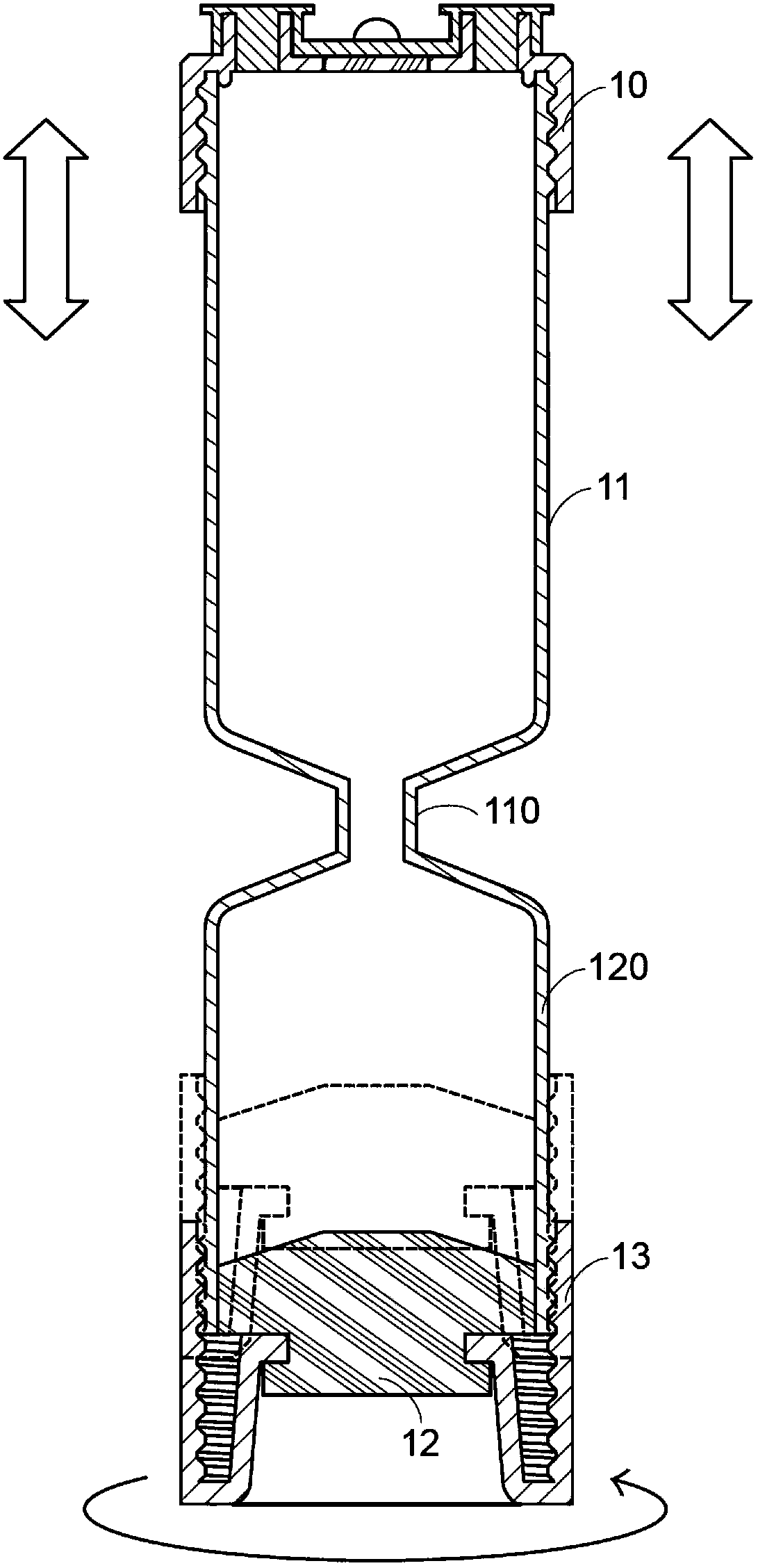
However, when the operator twists the bottom cover with his fingers, the direction of the force component will be perpendicular to the longitudinal axis of the main body 11 when the force is applied, so it is easy to cause the entire biological device to shake from side to side, resulting in the Clearly stratified upper liquid, middle liquid and lower liquid are mixed with each other

Method used


Image

  • Centrifuge tube structure
  • Centrifuge tube structure
  • Centrifuge tube structure

Examples


Embodiment Construction

[0079] The following examples are used to illustrate the content of the present invention, but not to limit the present invention. It should be noted that in the following embodiments and drawings, elements irrelevant to the present invention have been omitted and not shown.

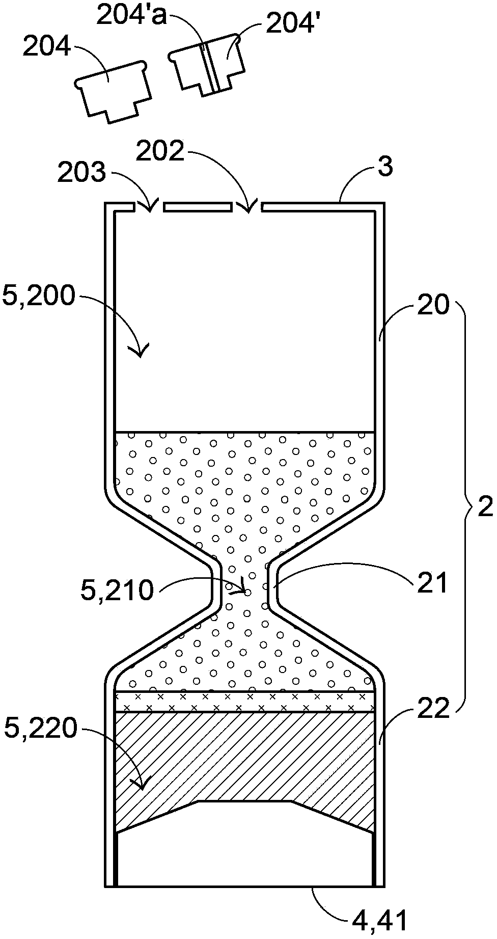
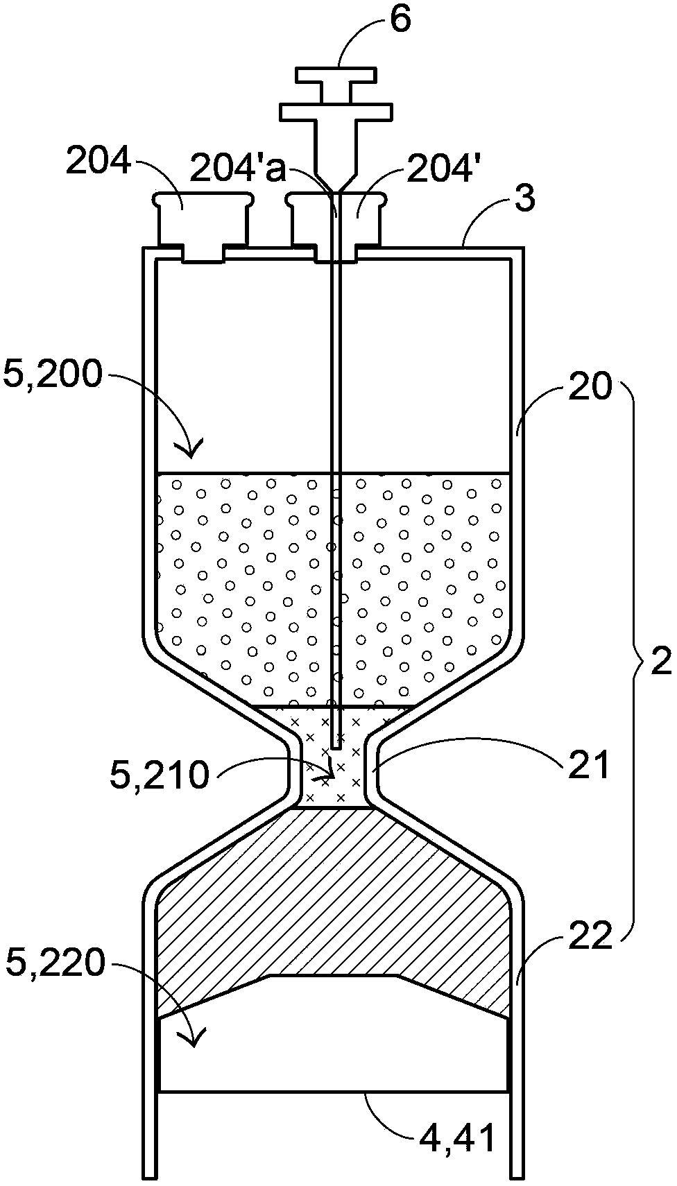
[0080]The main inventive spirit of the present invention is to disclose a centrifuge tube structure, which is used to accommodate the blood to be separated, and is doped with a small amount of anticoagulant to prevent the blood from coagulating during the operation. After the operator seals the blood in the centrifuge tube structure, the centrifuge tube structure containing the blood is placed in a general centrifuge to perform centrifugation. The principle is that due to the different specific gravity of various components contained in the blood, the blood in the centrifuge tube structure will be obviously stratified into three layers after using the centrifuge tube structure and centrifuge to perform t...


PUM


Abstract

The invention discloses a centrifuge tube structure which comprises a tube body, a first blockage body and a second blockage body, wherein the tube body is provided with a first holding groove, a second holding groove and a necking part; the necking part is connected with the first holding groove and the second holding groove, the first blockage body is fixed in the first holding groove and commonly defines a fixed volume space together with the first holding groove; the second blockage body moves along the second holding groove and commonly defines a variable volume space together with the second holding groove, wherein the necking part defines a communicating channel to communicate the fixed volume space with the variable volume space. The centrifuge tube structure is capable of ensuring disposable use, is simplified in structure design and brings convenience for production and manufacture.

Description

technical field [0001] The invention relates to a centrifuge tube structure, in particular to a centrifuge tube structure which is convenient for extracting a thin-layer solution. Background technique [0002] With the daily development of biomedical technology, the biomedical field has also conducted more and more complete research on human blood. Among them, the various components contained in the blood have their corresponding important functions. Therefore, if these components contained in the blood can be successfully separated and used as a medical auxiliary treatment, the current medical efficacy will be greatly improved. . At present, the common way to separate various components in blood is to put the test tube containing blood into the centrifuge and start it, so that after the blood in the test tube is centrifuged, the various components in the blood will present a simple layering . [0003] As mentioned above, after the test tube is centrifuged by the centrifu...

Claims


Application Information

Patent Timeline
Patent Type & Authority Applications(China)
IPC IPC(8): B01L3/14
CPCB01L2300/0858B01L2300/042B01L2300/046B01L3/14B01L2400/0478A61J1/2096B01D21/26B01L2400/0409B01L2200/026B01L3/5021B01D21/262B01D2221/10
Inventor 杨朝城
Owner 杨朝城
Learn More