Hardware tool discharging device and feeding equipment special for hardware tool discharging device

A technology of hardware tools and feeding equipment, which is applied in the direction of metal processing equipment, feeding devices, manufacturing tools, etc., can solve problems such as large safety hazards, low work efficiency, and high labor intensity of workers, so as to improve production efficiency and reduce labor costs. Strength, material saving effect

Inactive Publication Date: 2014-03-26
莒南县舜耕五金工具有限公司
View PDF10 Cites 4 Cited by
  • Summary
  • Abstract
  • Description
  • Claims
  • Application Information

AI Technical Summary

Problems solved by technology

[0003] In order to solve the trapezoidal hardware products formed by punching presses in the prior art, in order to save materials, it is necessary to manually turn over and feed the materials repeatedly, which has great potential safety hazards, high labor intensity of workers, and low work efficiency. The invention provides a hardware tool Unloading device and its special feeding equipment

Method used


Image

  • Hardware tool discharging device and feeding equipment special for hardware tool discharging device
  • Hardware tool discharging device and feeding equipment special for hardware tool discharging device
  • Hardware tool discharging device and feeding equipment special for hardware tool discharging device

Examples


Embodiment 1

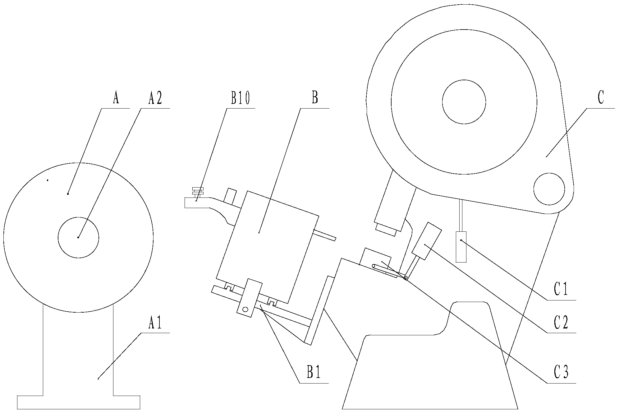
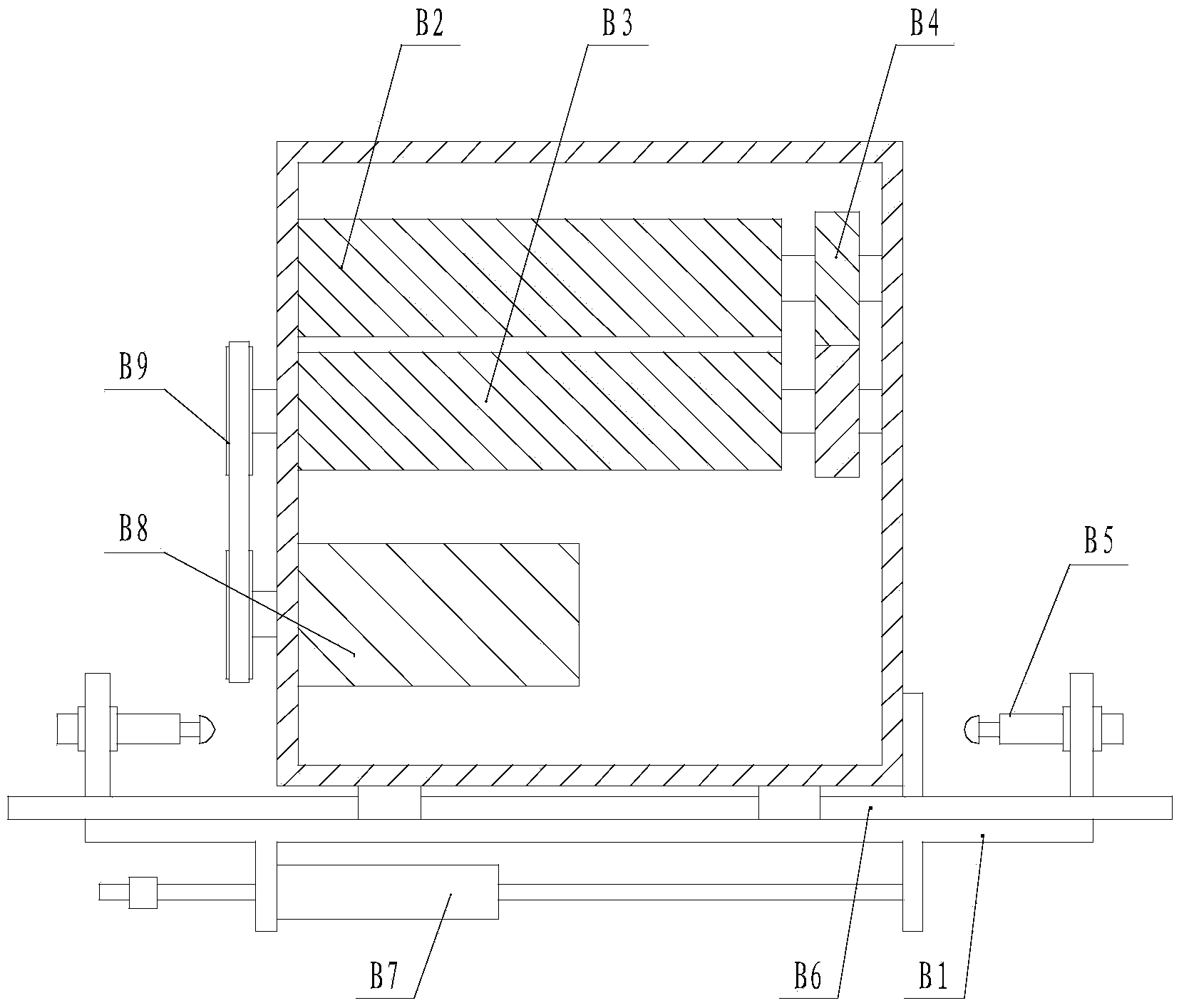
[0032] Embodiment 1: a hardware tool blanking device, including a punch C, on which a feed device B that can move left and right is provided; the feed device B includes a motor B8, a feed roller A B3 and a feed roller B B2, Motor B8 drives the feed roller B3 to rotate, and the feed roller B3 drives the feed roller B2 to rotate.

[0033] When this embodiment is in use, the function of moving left and right can be realized through the cooperation of the rollers with the cylinder or the oil cylinder.

Embodiment 2

[0034] Embodiment two: the feeding device B is installed on the punch press C through the frame A B1, a guide rail B6 is provided between the feeding device B and the frame A B1, and a cylinder C B7 is provided at the bottom of the frame A B1; A guiding device B10 is provided above the device B; a hydraulic buffer B5 is respectively provided on both sides of the feeding device B, and the hydraulic buffer B5 is fixedly connected to the frame A B1; the others are the same as the first embodiment.

Embodiment 3

[0035] Embodiment 3: The present invention also includes an automatic unwinding machine A, which includes a frame B A1 on which a turntable A2 is arranged; the others are the same as in Embodiment 2.

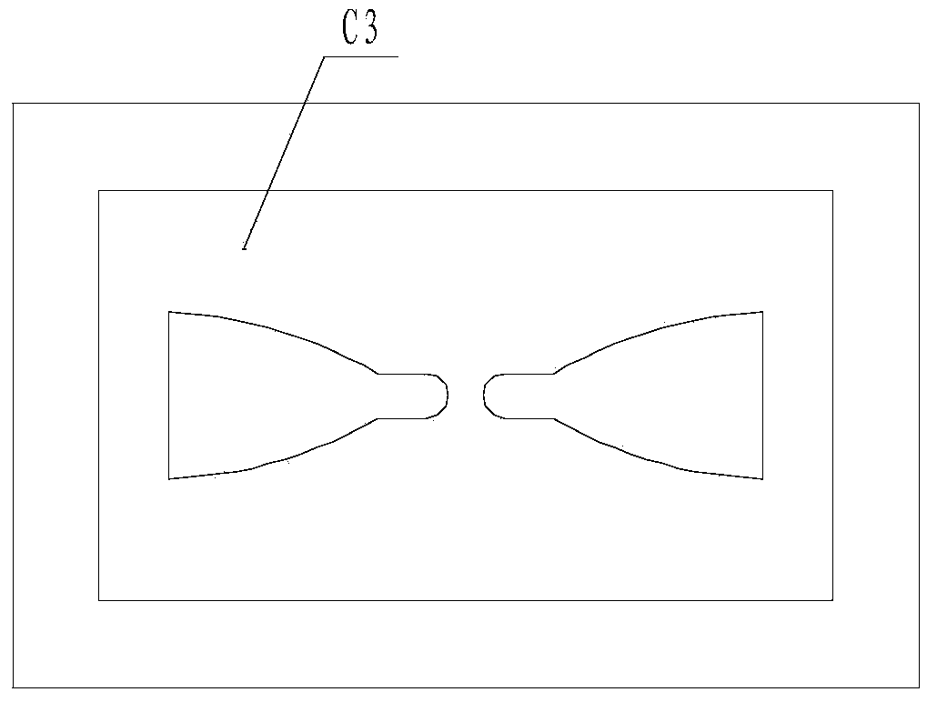
[0036] When the present invention is in use, it is used in conjunction with the automatic control system; for the convenience of calculation, the motor B8 is connected with the feed roller A B3 through the synchronous pulley B9, and the feed roller A B3 drives the feed roller B B2 through the gear B4; the punch C is provided with a cylinder A C1 is connected to cylinder B C2; cylinder B C2 is connected to the cam of symmetrical mold C3; cylinder A C1, cylinder B C2, cylinder C B7 and servo motor B8 are respectively connected to the automatic control system;

[0037] Design the specific automatic control system according to the specific mold, install the steel strip D on the turntable A2 of the automatic unwinding machine A, and the front end of the steel strip D passes through th...


PUM


Abstract

The invention discloses a hardware tool discharging device and feeding equipment special for the hardware tool discharging device, and belongs to the field of hardware tool machines. The hardware tool discharging device mainly comprises a punching machine, and a special feeding device capable of moving left and right is arranged on the punching machine. The special feeding device comprises a first rack, and a feeding device capable of moving left and right is arranged on the first rack and comprises a motor, a first feeding roller and a second feeding roller, wherein the motor drives the first feeding roller to rotate, and the first feeding roller drives the second feeding roller to rotate. A guide rail is arranged between the feeding device and the first rack, and a third air cylinder is arranged at the bottom of the first rack. The two sides of the feeding device are respectively provided with a hydraulic buffer, and the hydraulic buffers are fixedly connected to the first rack. According to the hardware tool discharging device and the feeding equipment special for the hardware tool discharging device, repeated turnover feeding of steel belts is avoided, materials are saved, batch forming of hardware products is easily achieved, labor intensity of workers is relieved, dependence on operation techniques of the workers is small, and energy consumption is reduced. The hardware tool discharging device is mainly used for batch production of hardware tools.

Description

technical field [0001] The invention belongs to the field of hardware tool machinery, and in particular relates to a hardware tool blanking device and special feeding equipment thereof. Background technique [0002] In the forming process of traditional hardware tools, the steel strip is generally cut into steel plates with equal distances after calculation, and then the workers hold the steel plates on the punching machine for stamping and forming. The existing trapezoidal and triangular hardware tools formed by punching presses need to be turned over and fed manually to save materials, but this feeding mode has the following defects: the workers hold the steel plate to feed the material, and stamping and forming on the punching machine, there is a greater safety hazard. Hidden dangers, and require workers to have high operating experience, the labor intensity of workers is high, the work efficiency is low, the energy consumption in the work process is large and the waste o...

Claims


Application Information

Patent Timeline
Patent Type & Authority Applications(China)
IPC IPC(8): B21D22/02B21D43/09
Inventor 徐春雷
Owner 莒南县舜耕五金工具有限公司
Why Eureka
Try Eureka