Two-stage lifting two-tail vehicle with two swinging ends for material piling and taking machine

A two-stage, reclaimer technology, applied in the directions of transportation and packaging, loading/unloading, etc., can solve the problems of rapid changes in the cylinder lever arm, high energy consumption of ground belt conveyors, and high positions of moving parts, and achieves continuous bulk material transportation. The effect of protecting the working environment and simple structure

Active Publication Date: 2014-03-26
DALIAN HUARUI HEAVY IND GRP CO LTD
View PDF13 Cites 8 Cited by
  • Summary
  • Abstract
  • Description
  • Claims
  • Application Information

AI Technical Summary

Problems solved by technology

However, this form is rarely used because the position of the moving parts is too high, the force and stroke of the cylinder are large, the force arm of the cylinder changes sharply, and the energy consumption of the ground belt conveyor is large.
[0004] Application No. 201120279715.7 of the Chinese patent "Stack-reclaimer Swing Type Lifting Tail Cart" discloses a hydraulic lift-type two-tail car that only involves functions such as stacking, straight-through, and return, but it cannot realize stacking and reclaiming machine stacking. The conversion of material, return and reclaim, straight-through and straight-feed functions, and the inability to change the posture of the rear swing section of the lift-type two-tail car at the same time during the conversion process, so as to adapt to the ground belt conveyor

Method used


Image

  • Two-stage lifting two-tail vehicle with two swinging ends for material piling and taking machine
  • Two-stage lifting two-tail vehicle with two swinging ends for material piling and taking machine

Examples


Embodiment Construction

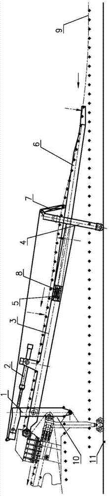
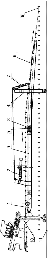
[0011] figure 1 and figure 2 It is a schematic diagram of the stacking state and the straight-through and return reclaiming states of a two-stage lifting two-tailed car with two ends of the stacker and reclaimer swinging at both ends of the present invention.

[0012] The two-stage lifting two-tail car that swings at both ends of this stacker-reclaimer is provided with an L-shaped swing beam 1, and the end of the long arm of the L-shaped swing beam 1 is hinged with the middle part of the main tail car 10 legs to form The middle part of arm is hinged with the middle part of the transverse long arm front end of T-shaped swing tailgate beam 3. The jib end of the L-shaped swing beam 1 is provided with a steering ring 12, and one end of the wire rope 13 is connected with the hydraulic cylinder 2 piston rod ends hinged on the vertical jib of the T-shaped swing tail beam 3 through the steering ring 12. The rear end of the transverse long arm of the T-shaped swing tail beam 3 is fi...


PUM


Abstract

The invention relates to a two-stage lifting two-tail vehicle with two swinging ends for a material piling and taking machine. A front-stage swing tail vehicle beam, namely a T-shaped swing tail vehicle beam 3, is driven by a hydraulic oil cylinder 2 to swing up and down, a rear-stage swing tail vehicle beam, namely a straight-line swing tail vehicle beam 6, swings along with the T-shaped swing tail vehicle beam 3 through a pulley system 7 at the same time, and two-stage swing action is realized by sharing one set of drive, so that material piling, material taking and straight through conditions are synchronously switched. The two-stage lifting two-tail vehicle has the technical and economic benefits that relative heights and angles of a tail vehicle belt conveyor and a ground surface belt conveyor are adjustable, so that an original tail vehicle and a ground surface angle are divided into two parts; the edge tensions of transition sections of the tail vehicle are balanced through the design of the belt conveyor that a concave arc section, a convex arc section and a concave arc section are connected, the distance and angle between the rear end of the tail vehicle and a ground surface belt are adjustable, and the problem of stop cleaning caused by belt flying, material scattering and the like in the transition sections of the ground surface and the tail vehicle is solved. The structure is simple, and the two-stage swing action is realized by utilizing one set of drive, so that material piling, material taking, straight through and straight taking conditions are synchronously switched. Meanwhile, the two-stage lifting two-tail vehicle is beneficial for environmental protection.

Description

technical field [0001] The invention relates to loading and unloading equipment for large bulk material storage yards. Background technique [0002] With the high development of modern logistics, the craftsmanship of bulk storage yards is more complex and diverse, and there are more functional requirements for bulk storage yard equipment stackers and reclaimers. The stacker-reclaimer is required to have the functions of stacking, turning and reclaiming, straight-through, and direct fetching. The swing-type lifting two-tail car is the most commonly used method. The swing-type lifting two-tail car is located between the main tail car and the ground belt conveyor. Its function limits the height of the movable second-tail car. It requires The length of the second tail car should be as small as possible. However, the large inclination angle and small lifting height lead to the inability to design a reasonable curve transition section according to the belt conveyor standard betw...

Claims


Application Information

Patent Timeline
Patent Type & Authority Applications(China)
IPC IPC(8): B65G65/28
Inventor 宋江波张瑞连吕明荟赵昱棠王英洁许宝雷
Owner DALIAN HUARUI HEAVY IND GRP CO LTD
Why Eureka
Try Eureka