Feeding nozzle of catalytic cracking unit

A feed nozzle, catalytic cracking technology, applied in the direction of catalytic cracking, cracking, injection device, etc., can solve the problem of inaccessible catalyst, etc., and achieve the effect of reducing coke formation

Active Publication Date: 2014-03-26
CHINA UNIV OF PETROLEUM (BEIJING)
View PDF8 Cites 7 Cited by
  • Summary
  • Abstract
  • Description
  • Claims
  • Application Information

AI Technical Summary

Problems solved by technology

[0007] In addition, for single-jet nozzles, the contact between the feed and the catalyst is good on the upflow surface but the catalyst cannot be contacted on the backflow surface, so that the actual catalyst-to-oil ratio in the reactor is lower than the nominal catalyst-to-oil ratio, or the feed-to-catalyst The micro contacts are not at their best

Method used


Image

  • Feeding nozzle of catalytic cracking unit
  • Feeding nozzle of catalytic cracking unit
  • Feeding nozzle of catalytic cracking unit

Examples


Embodiment Construction

[0044] The catalytic cracking feed atomizing nozzle of the present invention will be described below with reference to the accompanying drawings.

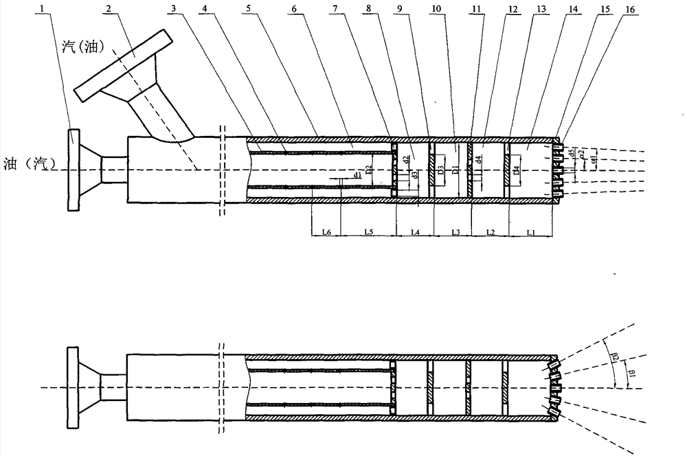
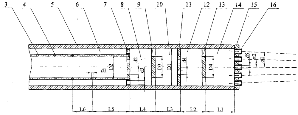
[0045] refer to figure 1 , the feed nozzle includes raw oil (steam) inlet, 2. steam (raw oil) inlet, 3. inner pipe steam distributor, 4. distribution hole, 5. outer pipe, 6. annular mixing chamber, 7. distributor, 8. First mixing chamber, 9. First intensive mixing baffle, 10. Second mixing chamber, 11. Redistributor, 12. Third mixing chamber, 13. Second intensive mixing baffle, 14. Fourth mixing Cavity, 15. nozzle base, 16. nozzle group, one end of the outer tube 5 has a raw material oil (steam) inlet 1, and the outer tube 4 has a steam (raw material) inlet 2, and the other end of the outer tube 5 has a nozzle base 15 , the front section of the nozzle base 15 is equipped with a nozzle 16, the outer pipe 5 has an inner pipe steam distributor 3, an annular mixing chamber 6 is arranged between the outer pipe 5 and the inner pipe stea...


PUM

PropertyMeasurementUnit
diameteraaaaaaaaaa

Abstract

The invention relates to a feeding nozzle of a catalytic cracking unit of an oil refinery. The feeding nozzle comprises an inner tube steam distributor 3, circumferential steam distributing holes 4, an outer tube 5, an annular space mixing cavity 6, top steam distributing holes 7, mixing cavities 8, 10, 12 and 14, reinforcing mixing baffles 10 and 13, a nozzle base body 15, nozzle groups 16 and the like, wherein a spraying section comprises specially designed nozzle groups 16 so as to form flat sector mist spray consisting of multistrand micro jets, thus well covering section of a lifting tube; furthermore, the catalyst can pass through the micro jets, so that the contact area of the oil mist jet flow of the multistrand micro jets and the catalyst is larger, the oil and the catalyst can well contact; as the upstream catalyst and the oil gas penetrate through the sector mist spray and eject through clearances between the micro jets, the catalyst and the oil gas cannot well contact, the catalyst cannot form eddy on the back of the sector jet flow, the hidden danger that the oil gas rewinds and touches the wall surface of the lifting tube so as to coke is eliminated.

Description

technical field [0001] The invention relates to a feed nozzle used for a catalytic cracking device in an oil refinery, belonging to the field of catalytic cracking equipment. Background technique [0002] The riser reactor is the core component of the catalytic cracking process. During the reaction process in the riser reactor, the raw oil enters the reactor through atomization, contacts with the catalyst, is vaporized by heat and reacts under the action of the catalyst. After feeding, the oil and gas generally stay in the reactor for 2-3 seconds. After the reaction is completed, it enters the oil separation system to stop the reaction. This process requires that after the raw oil is atomized into the reactor, it should be in contact with the catalyst quickly and evenly. The shorter the time required for full contact, the better, so as to facilitate the reaction process. In addition, after the contact between the feed and the oil agent is quickly realized, a uniform plug f...

Claims


Application Information

Patent Timeline
Patent Type & Authority Applications(China)
IPC IPC(8): C10G11/00C10G11/20B05B7/04
Inventor 王江云毛羽王娟毛林
Owner CHINA UNIV OF PETROLEUM (BEIJING)
Why Eureka
Try Eureka