Turbonator grounding device and method

A technology of steam turbine generator and grounding device, applied in electromechanical devices, electrical components, structural connections, etc., can solve the problems of inability to eliminate high-frequency shaft voltage peaks, no good solution, and high rotation speed

Inactive Publication Date: 2014-03-26
CHINA SHENHUA ENERGY CO LTD +2
View PDF5 Cites 8 Cited by
  • Summary
  • Abstract
  • Description
  • Claims
  • Application Information

AI Technical Summary

Problems solved by technology

However, the existing grounding brushes often fail due to the high speed at which the shaft surface at the turbine end of the generator rotates, and e

Method used


Image

  • Turbonator grounding device and method
  • Turbonator grounding device and method
  • Turbonator grounding device and method

Examples


Embodiment Construction

[0022] Specific embodiments of the present invention will be described in detail below in conjunction with the accompanying drawings. It should be understood that the specific embodiments described here are only used to illustrate and explain the present invention, and are not intended to limit the present invention.

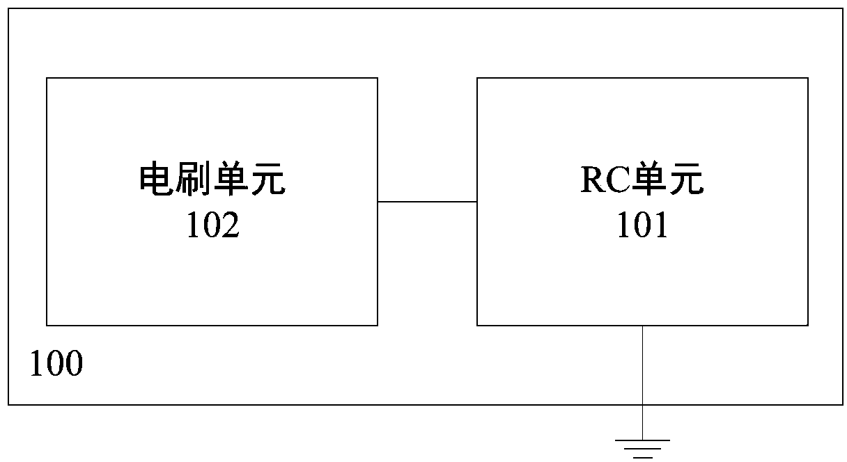
[0023] figure 1 It is a structural block diagram of a grounding device for a turbogenerator according to an embodiment of the present invention. Such as figure 1 As shown, a turbogenerator grounding device 100 provided by the present invention includes: an RC unit 101 and a brush unit 102, wherein the RC unit 101 is configured to be grounded at one end and connected to the brush unit 102 at the other end; And the brush unit 102 is configured to be in electrical contact with the exciter end shaft of the turbogenerator.

[0024] Through the above technical solution, an RC unit 101 is set between the exciter end shaft of the turbogenerator and the ground, and th...


PUM

PropertyMeasurementUnit
Resistanceaaaaaaaaaa
Insulation resistance valueaaaaaaaaaa
Capacitanceaaaaaaaaaa

Abstract

The invention discloses a turbonator grounding device and method. The turbonator grounding device comprises an RC unit and an electric brush unit, wherein one end of the RC unit is grounded, the other end of the RC unit is connected with the electric brush unit, and the electric brush unit is in electrical contact with an end axle of an exciting dynamo of a turbonator. By means of the technical scheme, since the RC unit is arranged between the end axle of the exciting dynamo of the turbonator and the ground, resistance can effectively eliminate electrostatic charges to reduce shaft currents; the adding of capacitance can reduce the specific value of shaft-to-ground capacitance and shaft-to-ground voltage, so that a high-frequency voltage peak is reduced.

Description

technical field [0001] The invention relates to the field of conductive connection, in particular to a grounding device and method for a turbogenerator. Background technique [0002] For a large turbogenerator set with a static excitation system, the high-frequency pulse signal generated by the static excitation system is superimposed on the basic shaft voltage to generate a shaft voltage. The magnitude of the shaft voltage varied from case to group. Generally, the larger the capacity of the unit, the larger the air-gap flux and the more obvious the asymmetry of the structure, and the larger the harmonic component in the magnetic field, the saturation degree of the iron core and the unevenness of the stator, the greater the peak value of the shaft voltage. higher. The waveform of the shaft voltage has complex harmonic components, and the unit with static controllable rectification excitation has a high pulse component in the shaft voltage waveform. [0003] With the incre...

Claims


Application Information

Patent Timeline
IPC IPC(8): H02K11/00H02K13/00H02K11/20
Inventor 王绍宇
Owner CHINA SHENHUA ENERGY CO LTD
Why Eureka
Try Eureka