
Half-bridge driving circuit

A technology of half-bridge drive and half-bridge circuit, which is applied to electrical components, output power conversion devices, etc., and can solve problems such as slow discharge speed

Inactive Publication Date: 2014-03-26
SHENZHEN OCEANS KING LIGHTING ENG CO LTD +1
View PDF4 Cites 14 Cited by
  • Summary
  • Abstract
  • Description
  • Claims
  • Application Information

AI Technical Summary

Problems solved by technology

[0006] Based on this, it is necessary to provide a half-bridge drive circuit that accelerates the discharge speed in view of the problem that the traditional half-bridge drive circuit discharges the control terminals of the upper and lower bridges at a slower rate.

Method used


Image

  • Half-bridge driving circuit
  • Half-bridge driving circuit

Examples


Embodiment Construction

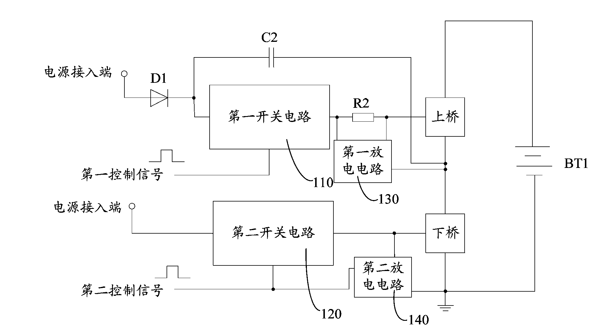
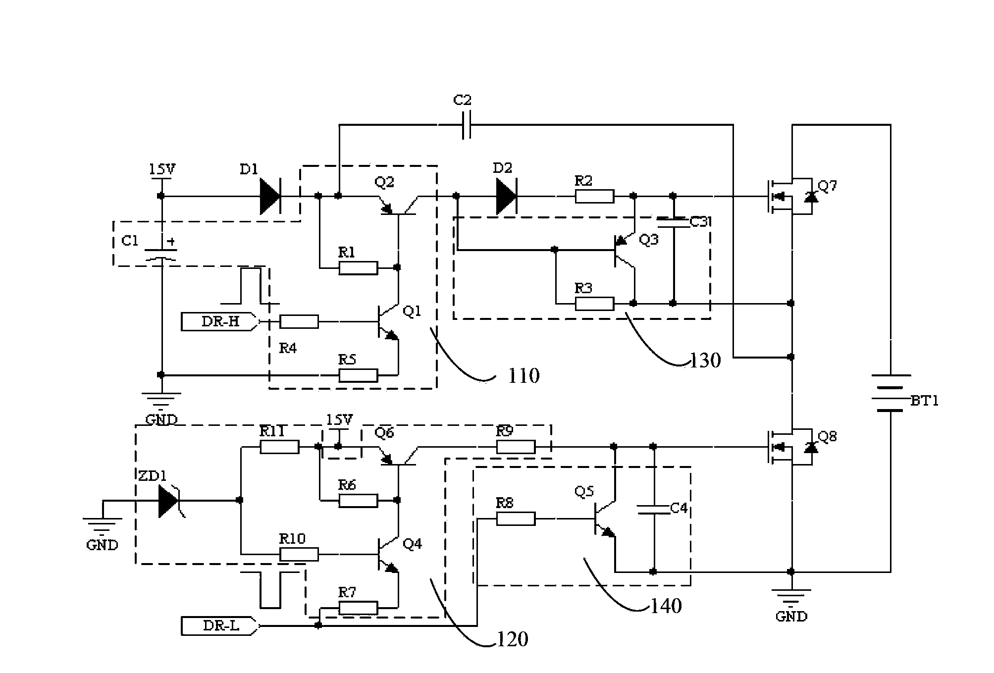
[0019] A half-bridge drive circuit, such as figure 1 As shown, it includes a bootstrap circuit, a half-bridge circuit, a first switch circuit 110 , a second switch circuit 120 , a first discharge circuit 130 , a second discharge circuit 140 and a bias unit. In this embodiment, the bias unit is the first current-limiting resistor R2, and other components capable of generating the required voltage drop may also be used in other embodiments. The bootstrap circuit includes a first diode D1 and a bootstrap capacitor C2. The anode of the first diode D1 is provided with a power access terminal, the cathode is connected to one end of the bootstrap capacitor C2, and the other end of the bootstrap capacitor C2 is connected to the half-bridge The common terminal of the upper bridge and the lower bridge of the circuit, the upper bridge and the lower bridge of the half bridge circuit can be a field effect transistor (MOSFET) or an insulated gate bipolar transistor (IGBT), where the input t...


PUM


Abstract

The invention discloses a half-bridge driving circuit which comprises a bootstrap circuit and a half-bridge circuit, and further comprises a first switch circuit, a second switch circuit, a first discharge circuit and a second discharge circuit, wherein the bootstrap circuit comprises a diode and a capacitor; the first switch circuit is powered on when a first control signal is in high level and is powered off in low level; the second switch circuit is powered on when a second control signal is in low level and is powered off in high level; the first discharge circuit is powered off when the first switch circuit is powered on and is powered on when the first switch circuit is powered off; the second discharge circuit is powered on when the second control signal is in high level and is powered off in low level; the on / off states of the two switch circuits are changed by changing the input control signals so as to control the on / off of upper and lower bridges; when the first discharge circuit is powered on, a control end of the upper bridge can be controlled to discharge electricity so as to accelerate the upper bridge to be closed; when the second discharge circuit is powered on, a control end of the lower bridge can be controlled to discharge electricity so as to accelerate the lower bridge to be closed. The electricity discharge speeds of the control ends of the upper bridge and the lower bridge are respectively accelerated through the first discharge circuit and the second discharge circuit.

Description

technical field [0001] The invention relates to a driving circuit of a switching power supply, in particular to a half-bridge driving circuit. Background technique [0002] Switching power supply is a kind of power supply that uses modern power electronic technology to control the time ratio of switching on and off to maintain a stable output voltage. It has a series of advantages such as small size and high efficiency, and is widely used in various electronic products. In a high-power switching power supply, it is necessary to use a half-bridge drive circuit to drive the half-bridge circuit, but the driving of the high-end side of the half-bridge drive circuit requires high voltage to achieve, so generally an integrated circuit with a bootstrap function is used as the half-bridge Drive circuit. [0003] A half-bridge circuit is usually realized by two semiconductor field effect transistors (MOSFETs) or insulated gate bipolar transistors (IGBTs), where the drain (or collect...

Claims


Application Information

Patent Timeline
Patent Type & Authority Applications(China)
IPC IPC(8): H02M1/088
Inventor 周明杰管伟芳
Owner SHENZHEN OCEANS KING LIGHTING ENG CO LTD
Learn More