Ignition control circuit of downhole electric detonator for perforation

An ignition control, electric detonator technology, applied in wellbore/well components, production fluids, earth-moving drilling, etc., can solve the problems of perforating gun rupture, electric detonator detonation, circuit short circuit, etc.

Inactive Publication Date: 2014-04-02
CHINA NAT PETROLEUM CORP CHUANQING DRILLING ENG CO LTD
View PDF6 Cites 12 Cited by
  • Summary
  • Abstract
  • Description
  • Claims
  • Application Information

AI Technical Summary

Problems solved by technology

[0006] 1. In actual use, the coded grading perforation meter cannot reliably connect to the downhole electric detonator, and the electric detonator is often detonated due to accidental conduction of the circuit and connected to the ignition circuit, resulting in misperforation engineering accidents
[0007] 2. After the electric detonator detonates the perforating gun, the perforating gun breaks and pours into the well fluid, which will cause a short circuit

Method used


Image

  • Ignition control circuit of downhole electric detonator for perforation
  • Ignition control circuit of downhole electric detonator for perforation
  • Ignition control circuit of downhole electric detonator for perforation

Examples


Embodiment 1

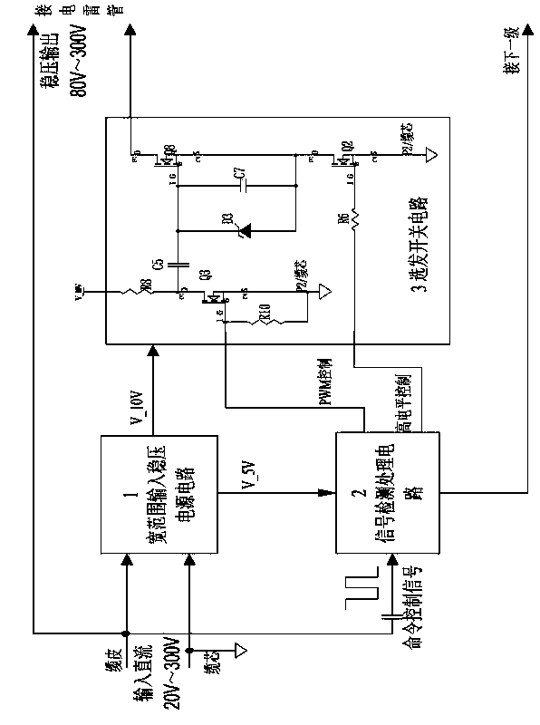
[0030] Refer to the attached figure 1 , A preferred embodiment of the present invention is: the hair selection switch circuit 3 of the present invention is composed of resistors R6, R8, R10, capacitors C5, C7, Zener diode D3, field effect transistors Q2, Q3, Q8. The connection relationship is: the gate of Q3 is connected to the PWM control terminal of the signal detection control circuit; one end of R10 is connected to the gate of Q3, the other end is connected to the source of Q3 and grounded; one end of R8 is connected to 10V power supply, and the other end is connected to the drain of Q3; one end of C5 is connected to The drain of Q3, the other end is connected to the grid of Q8, the cathode of D3 is connected to the grid of Q8, and the anode is connected to the drain of Q2; one end of C7 is connected to the grid of Q8, and the other end is connected to the source of Q8; the drain of Q8 is connected to one end of the electric detonator; one end of R6 Connect to the high-lev...

Embodiment 2

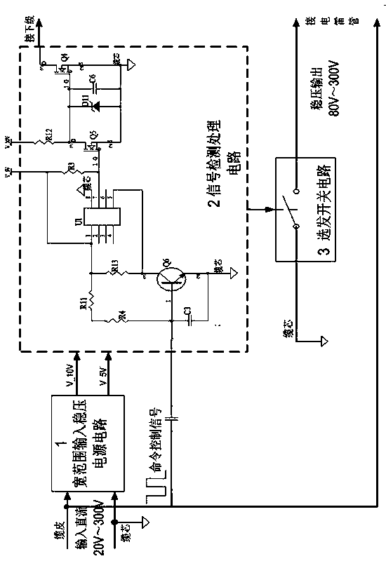
[0034] Refer to the attached figure 2 Another preferred embodiment of the present invention is: the signal detection processing circuit 2 of the present invention is composed of resistors R3, R4, R11, R12, R13, capacitors C3, C6, diode D11, transistor Q6, field effect transistor Q4, Q5 is composed of single-chip microcomputer U1. R4, R11, R13, C3 and Q6 form an amplifying circuit, which is used to amplify the command signal, output from the collector of Q6, the 5th pin of U1 is connected to the collector of Q6, the 1st pin of U1 is connected to the 5V power supply, and the 8th pin Connect the cable core (ground), connect one end of R3 and the gate of Q5 with pin 7, connect the other end of R3 to a 5V power supply, connect one end of R12 to a 10V power supply, and connect the other end to the drain of Q5, the cathode of D11, one end of C6 and the gate of Q4 The source of Q5 is connected to the anode of D11, the other end of C6 and the source of Q4 are connected to the cable c...

Embodiment 3

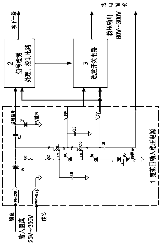
[0038] Refer to the attached image 3 , another preferred embodiment of the present invention is: wide-range input regulated power supply circuit 1 includes five diodes D1, D2, D5, D6, D7; two resistors R1 and R2; four capacitors C1, C8, C9, C10; 2 CMOS field effect transistors Q1, Q10. The connection relationship is: the anode of D2 is connected to the cable sheath, the cathode is connected to one end of R1, the other end of R1 is connected to one end of R2, the other end of R2 is connected to the grid of Q1, one end of C1 and the cathode of D6. The other end of C1 is connected to the cable core (ground), the anode of D6 is connected to the grid of Q10 and the cathode of D1, the anode of D1 is connected to the anode of D5, and the cathode of D5 is connected to the cable core (ground). The drain of Q10 is connected to one end of R1 and one end of C1, the other end of C1 is connected to the cathode of D7, and the anode of D7 is connected to the cable core (ground); the source ...


PUM


Abstract

The invention discloses an ignition control circuit of a downhole electric detonator for perforation. The ignition control circuit comprises a wide-input-range power supply voltage stabilizing circuit, a signal detection and processing circuit and an ignition selecting switch circuit, wherein the wide-input-range power supply voltage stabilizing circuit is used for stabilizing voltage and then outputting direct current of 10V and direct current of 5V when direct current of 20-40V is input to a downhole ignition control circuit by a ground system through a single-core cable, so as to supply power to the signal detection and processing circuit and an ignition switch circuit; the signal detection and processing circuit is used for receiving ignition control commands from the ground system, controlling the connection/disconnection of the ignition selecting switch circuit according to the commands and controlling the detonation of the electric detonator; the ignition selecting switch circuit is used for being connected with the electric detonator. The ignition control circuit has the advantages that the circuit access of the downhole electric detonator during detonation can be realized safely and reliably, meanwhile, the detonation circuit access of the electric detonator resulting from accidental circuit conduction can be prevented, and the effect of protecting and igniting a detonation circuit can also be exerted under the extreme cases that the detonation circuit is short-circuited.

Description

[0001] technical field [0002] The invention relates to the technical field of electric detonator ignition control technology in downhole cluster control perforation. Cluster control perforation is a perforation technology that can realize low cost and high benefit in the exploitation of unconventional natural gas (shale gas, etc.), and belongs to Field of oil and gas well perforating instruments. Background technique [0003] In the exploitation of unconventional natural gas, because the shale gas reservoir is thin, the reservoir is numerous and discontinuous, when using the conventional tubing transmission perforation and cable transmission perforation, the perforating gun needs to be lifted and lowered many times, which has a large workload and high cost. Therefore, a perforation technology that can realize low-cost and high-efficiency oil and gas well development is needed. Clustered perforation technology came into being under this background. This technology uses a s...

Claims


Application Information

Patent Timeline
Patent Type & Authority Applications(China)
IPC IPC(8): E21B43/1185
Inventor 陈锋唐凯孙伟张勇张雄辉胡超宏王海欧跃强
Owner CHINA NAT PETROLEUM CORP CHUANQING DRILLING ENG CO LTD
Why Eureka
Try Eureka