Optical fiber F-P cavity high-voltage sensor

A high-pressure sensor, F-P technology, applied in the direction of fluid pressure measurement, instruments, and measuring devices using optical methods, to achieve stable performance, high frequency response, and ensure measurement accuracy and reliability.

Inactive Publication Date: 2014-04-02
THE THIRD ENG CORPS RES INST OF THE HEADQUARTERS OF GENERAL STAFF PLA
View PDF8 Cites 15 Cited by
  • Summary
  • Abstract
  • Description
  • Claims
  • Application Information

AI Technical Summary

Problems solved by technology

However, at present, there are few optical fiber sensors that can be directly used for dynamic high-voltage measurement in harsh environments (such as high temperature, high pressure, strong electromagnetic interference, etc.), such as explosion shock wave pressure measurement in the field of military industry production and strategic and tactical weapon development.

Method used


Image

  • Optical fiber F-P cavity high-voltage sensor
  • Optical fiber F-P cavity high-voltage sensor
  • Optical fiber F-P cavity high-voltage sensor

Examples


Embodiment Construction

[0015] The accompanying drawings illustrate specific embodiments of the present invention.

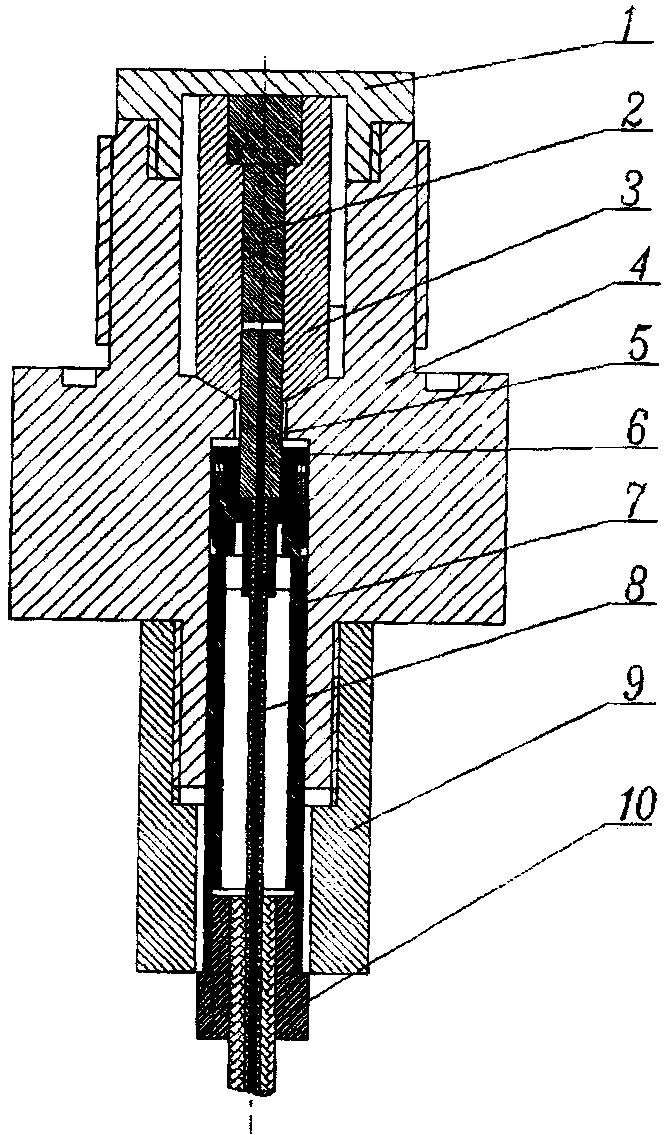
[0016] Such as figure 1 As shown: the present invention consists of a diaphragm body 1, an upper ceramic ferrule 2, a support cylinder 3, a mounting shell 4, a lower ceramic ferrule 5, a ferrule fixing cap 6, a guide positioning rod 7, an optical fiber 8, a protective cover 9, The fixed joint 10 forms. The diaphragm body 1 and the front end of the installation housing 4 are fixed to form the pressure-sensitive surface of the sensor. The upper ceramic ferrule 2 is placed in the support cylinder 3. The upper end surfaces of the two are flush and in close contact with the diaphragm body 1. The support cylinder 3 A conical contact surface is adopted between the lower end surface of the lower end face of the housing and the installation shell 4, the lower ceramic ferrule 5 (with pigtail) is fixed together with the guide positioning rod 7 through the ferrule fixing cap 6, and inserted into ...


PUM

PropertyMeasurementUnit
reflectanceaaaaaaaaaa

Abstract

The invention discloses an optical fiber F-P cavity high-voltage sensor, which comprises a diaphragm body, an upper ceramic insertion core, a support cylinder, a mounting shell, a lower ceramic insertion core, an insertion core fixing cap, a guide positioning rod, an optical fiber, a protection sleeve and a fixing joint; the diaphragm body is fixed with the front end of the mounting shell to form a pressure sensing surface of the sensor; the upper ceramic insertion core is arranged in the support cylinder; the upper end surfaces of the upper ceramic insertion core and the support cylinder are level and are tightly contacted with the diaphragm body; a conical contact surface is adopted between the lower end surface of the support cylinder and the mounting shell; the lower ceramic insertion core (with a tail fiber) and the guide positioning rod are fixed together by the insertion core fixing cap and are arranged in the mounting shell; an F-P cavity is formed between the lower end surface of the upper ceramic insertion core and the upper end surface of the lower ceramic insertion core; the protection sleeve is screwed into the lower part of the mounting shell; the optical fiber with an optical fiber protection sleeve is fixed at the lower end of the protection sleeve by the fixing joint. The optical fiber F-P cavity high-voltage sensor is simple in structure, convenient and fast to manufacture and low in cost.

Description

technical field [0001] The invention belongs to the technical field of optical fiber sensing, in particular to a large-range high-pressure high-frequency response sensor based on an optical fiber F-P cavity. Background technique [0002] Since the 1970s, along with the birth of low-loss optical fiber and the rapid development of optical fiber communication technology, optical fiber sensing technology has gradually developed into one of the high-tech countries in the world. Optical fiber sensors use light waves as information carriers and optical fibers as information transmission media to sense and measure measured parameters. It is precisely because of the difference between the optical fiber sensor and the traditional electronic sensor in the information carrier and transmission medium that the optical fiber sensor has the incomparable advantages of the traditional electronic sensor: 1) The optical fiber sensor is a passive device with good electrical insulation and resist...

Claims


Application Information

Patent Timeline
Patent Type & Authority Applications(China)
IPC IPC(8): G01L11/02G01L23/00
Inventor 余尚江陈晋央杨吉祥郭士旭周会娟贾超黄刘宏
Owner THE THIRD ENG CORPS RES INST OF THE HEADQUARTERS OF GENERAL STAFF PLA
Why Eureka
Try Eureka