Underwater wireless power and signal transmission system based on dual-frequency point resonant cavity

A signal transmission system, wireless energy technology, applied in transmission systems, electrical components, etc., can solve problems such as poor speed and quality, and achieve the effect of improving speed and quality

Active Publication Date: 2014-04-02
哈尔滨传能科技有限公司
View PDF6 Cites 7 Cited by
  • Summary
  • Abstract
  • Description
  • Claims
  • Application Information

AI Technical Summary

Problems solved by technology

[0003] The purpose of the present invention is to solve the current problem of poor speed and quality of underwater wireless power transmission and underwater signal transmission and communication, thereby providing an underwater wireless power and signal transmission system based on a dual-frequency resonant cavity

Method used


Image

  • Underwater wireless power and signal transmission system based on dual-frequency point resonant cavity
  • Underwater wireless power and signal transmission system based on dual-frequency point resonant cavity
  • Underwater wireless power and signal transmission system based on dual-frequency point resonant cavity

Examples


specific Embodiment approach 1

[0034] Specific implementation mode 1. Combination figure 1 Describe this specific embodiment, an underwater wireless power and signal transmission system based on a dual-frequency point resonant cavity, which is characterized in that: it includes a transmitting circuit, a receiving circuit and a dual-frequency point transceiver integrated resonant cavity;

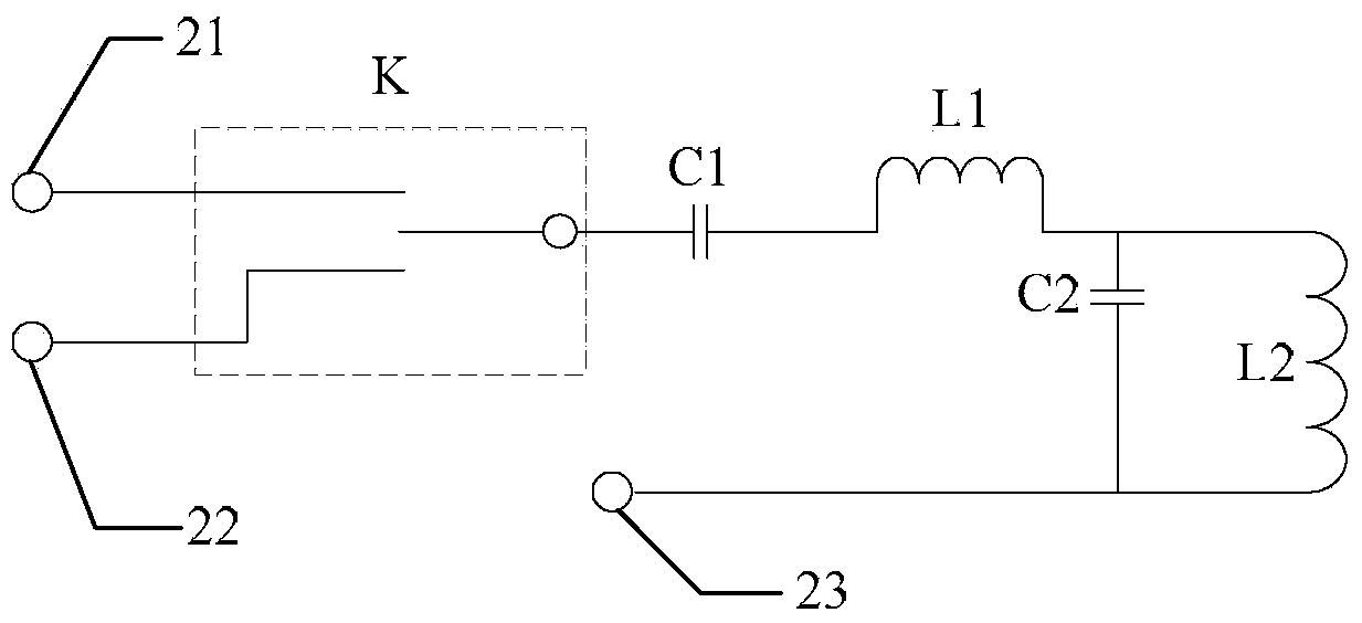
[0035] The integrated resonant cavity for transmitting and receiving includes a receiving and transmitting switch K, a resonant capacitor C1, a resonant coil L1, a resonant capacitor C2 and a resonant coil L2;

[0036] The first static end of the transceiver switch K is the receiving end of the dual-frequency point transceiver integrated resonator; the second static end of the transceiver switch K is the transmitting end of the dual-frequency transceiver integrated resonator; terminal is connected with one end of the resonant capacitor C1; the other end of the resonant capacitor C1 is connected with one end of the resonant...

specific Embodiment approach 2

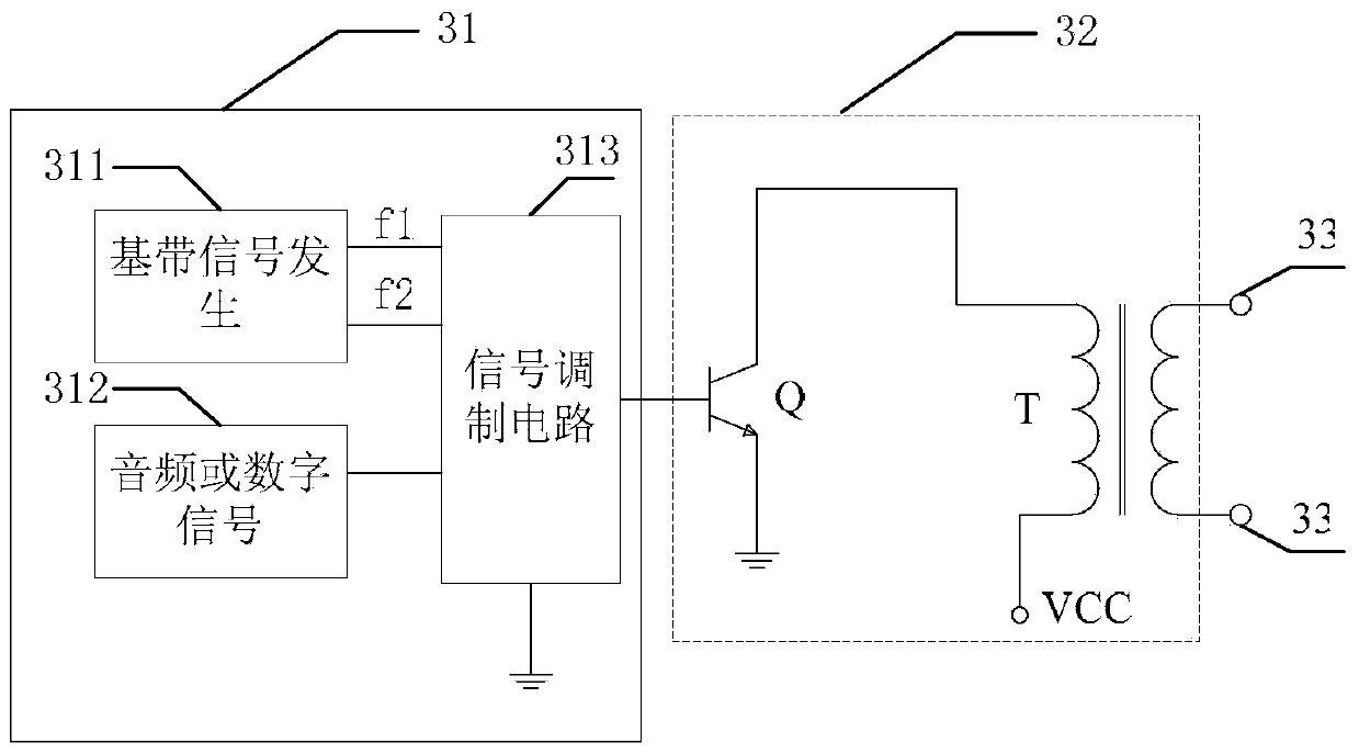
[0051] Specific Embodiment 2. The difference between this specific embodiment and the underwater wireless power and signal transmission system based on dual-frequency resonators described in specific embodiment 1 is that the signal modulation circuit 313 is a 2FSK modulation circuit; the signal demodulation Circuit 45 is a 2FSK demodulation circuit.

specific Embodiment approach 3

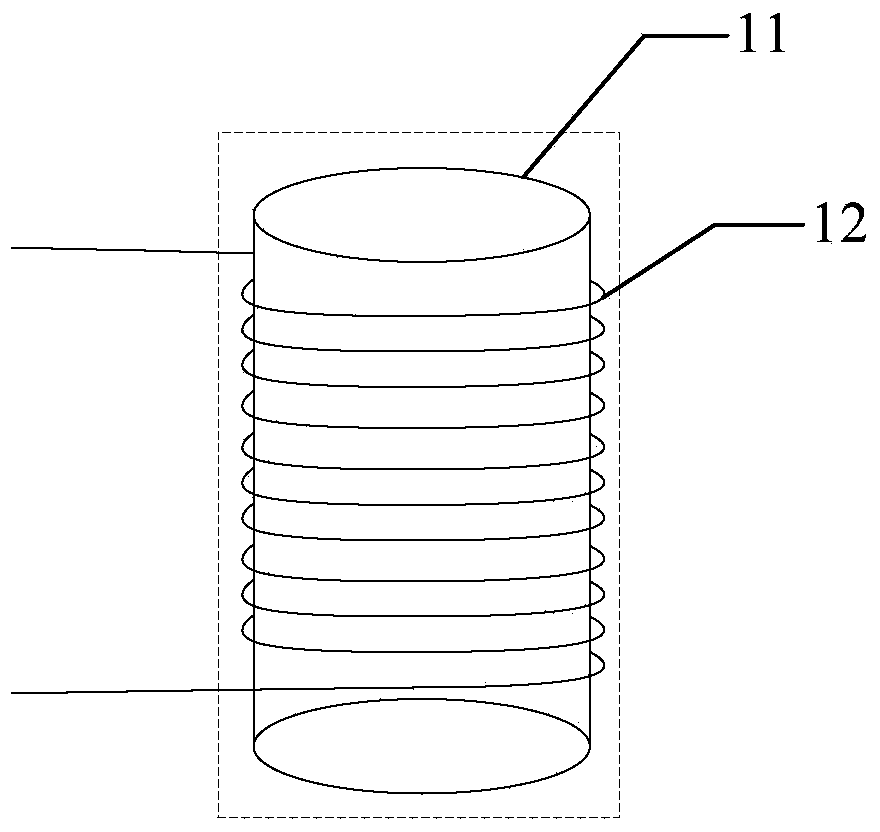
[0052] Specific Embodiment 3. The difference between this specific embodiment and the underwater wireless power and signal transmission system based on dual-frequency resonant cavity described in specific embodiment 1 is that the first resonant coil L1 and the second resonant coil L2 The structure is the same, the No. 1 resonant coil L1 includes a cylindrical magnetic core and an excitation wire, and the excitation wire is wound outside the cylindrical magnetic core.


PUM


Abstract

The invention discloses an underwater wireless power and signal transmission system based on a dual-frequency point resonant cavity and relates to the technical fields of wireless power transmission and near-field magnetic communication. In order to solve the problems of low speed and poor quality of underwater wireless power transmission and underwater signal transmission communication at present, the system provided by the invention is characterized in that the signal is transmitted through a high-speed alternating current magnetic field; a digital signal is modulated into a high-frequency carrier signal in a 2FSK mode; the modulated signal is converted into a high-frequency alternating current magnetic field and then emitted by a power amplification and dual resonant cavity circuit structure; at the receiving end, an integrated transceiver resonant cavity generates resonance after receiving a high-frequency magnetic field; only signal transmission can be carried out due to a small coupling coefficient in a long-distance condition; the original signal at the transmitting end can be obtained after signal amplification and demodulation is carried out on small resonated current; energy transmission is carried out during signal transmission due since the coupling coefficient is large when a coil generates coupling resonance in a short distance. Therefore, the system is applicable to underwater wireless power and signal transmission.

Description

technical field [0001] The invention relates to the technical fields of wireless power transmission and near-field magnetic communication, in particular to an underwater wireless power transmission and signal transmission system. Background technique [0002] The power transmission between underwater equipment and between underwater equipment and surface equipment usually needs to surface the equipment, which undoubtedly limits the working time, working area and cost of underwater equipment, and traditional underwater equipment communication is generally The sonar system is used, and the transmission of sound waves in water will be affected by temperature, salt concentration, water flow, underwater noise, etc., the speed and quality of communication will be greatly affected, and it is easy to be interfered by humans, which will undoubtedly affect the underwater working equipment. normal work caused great difficulties. Contents of the invention [0003] The present inventi...

Claims


Application Information

Patent Timeline
Patent Type & Authority Applications(China)
IPC IPC(8): H04B1/40H04B1/44H04B13/02
Inventor 朱春波姜金海魏国宋凯逯仁贵
Owner 哈尔滨传能科技有限公司
Why Eureka
Try Eureka