Solar plant

A solar device, a technology of solar energy, applied in the field of solar energy, can solve the problems of not having a preferred direction, not allowing efficient optical concentration, etc.

Inactive Publication Date: 2014-04-02
ABENGOA SOLAR NEW TECH SA
View PDF6 Cites 4 Cited by
  • Summary
  • Abstract
  • Description
  • Claims
  • Application Information

AI Technical Summary

Problems solved by technology

There are some problems in the prior art examples of these converters which do not allow to achieve a sufficiently high efficiency or maintain a high optical concentration, mainly due to the directionality of the emitted light after conversion - which does not have a preferred direction

Method used


Image

  • Solar plant
  • Solar plant
  • Solar plant

Examples


Embodiment Construction

[0088] Below are the attached drawings 1 to Figure 6 A description of the recommendation model of the present invention with the help of .

[0089] Recommended Model 1

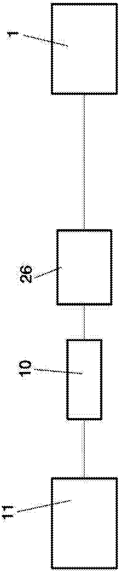
[0090] The invention as shown in the accompanying drawings refers to a method for obtaining energy (20) from solar radiation under optimal utilization of the solar spectrum (cf. Figure 5 ) solar installations.

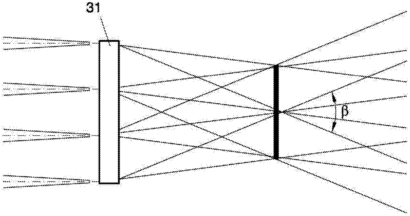
[0091] Such as Figure 1a As can be seen in , the beam generated by the first lens-type concentrator device (31) has some divergence. The divergence associated with these first concentrator means (31) is linked to the degree of concentration achieved. The greater the concentration attempted, the more divergent the output beam will be. This phenomenon is explained by the etendue conservation theorem. In a three-dimensional system, n 2 ·A·sen 2 (β / 2)=cte, where n is the refractive index of the medium, A is the area of ​​the element belonging to the first concentrating means (31) where concentrat...


PUM


Abstract

The invention enables the transformation of solar energy using the majority of the solar spectrum with a very efficient yield. The invention comprises at least one solar collector (11) that comprises a focal point and is suitable for collecting solar radiation and concentrating it in the focal point; a solar laser device (10) for transforming the radiation received from the focal points into laser radiation; and a receiver (1) and / or a solar reactor (21) suitable for receiving the radiation from the laser device (10) and transforming it into another type of energy. The invention can comprise flexible light guides (8) or flat mirrors (26) for transporting the radiation received from the laser device to the solar reactor (21) and / or the receiver (1). It can also comprise photovoltaic cells (18) inserted between the collectors and the laser devices for transforming the concentrated radiation of the focal points into electricity and letting through the radiation that they do not transform to the laser devices.

Description

technical field [0001] The invention may be included in the field of solar technology. The object of the present invention relates to a solar installation enabling the conversion of a large part of the spectrum of incoming solar radiation into electrical or thermal energy. Background technique [0002] The development of solar energy presents several challenges. One of these challenges is the capture and concentration of solar energy, a problem that is currently being extensively researched, developed and applied. In this regard, the challenge for solar installations is to: maximize the concentrator-collector C / Cmax ratio (where C is the concentration and Cmax = 1 / sine (half the acceptance rate) is the theoretical maximum concentration), minimize the geometry Losses - cosine effects, shading and blocking between trackers, optical and thermal losses, and reducing device cost to a level that makes the technology competitive with other energy sources. Importantly, maximizing...

Claims


Application Information

Patent Timeline
Patent Type & Authority Applications(China)
IPC IPC(8): H01S5/026H01L31/04F24J2/07G02B6/42F24S20/20
CPCY02E10/52F03G6/06H01L31/0522H01L31/052H01S3/0915H01L31/0543H01L31/0547G02B6/02314H01L31/055H01S3/005H01S3/06704H01S3/06741H01S3/08059H01S3/23Y02E10/46H01S5/026
Inventor 胡安·帕布洛·努内斯布特鲁曼努埃尔·格拉斯特里拉
Owner ABENGOA SOLAR NEW TECH SA
Why Eureka
Try Eureka