Eureka AIR delivers breakthrough ideas for toughest innovation challenges, trusted by R&D personnel around the world.

Anti-rolling devices, floating foundations and offshore wind turbines

An anti-rolling device and basic technology, applied in the direction of wind turbines, wind motor combinations, wind turbines consistent with the wind direction, etc., can solve the problems of no engineering practical value, slow phase response, narrow frequency range, etc., to achieve convenient manufacturing, The effect of reducing the range of motion and improving exercise performance

Active Publication Date: 2016-09-14
XINJIANG GOLDWIND SCI & TECH CO LTD
View PDF5 Cites 3 Cited by
  • Summary
  • Abstract
  • Description
  • Claims
  • Application Information

AI Technical Summary

Problems solved by technology

Anti-rolling water tanks are mainly divided into two types: passive and active. Among them, the frequency range of the passive type is narrow, and there will be adverse consequences of increased roll outside the allowable frequency range; the active control type is mainly controlled by opening / closing valves, but the phase response Hysteresis and complex control limit its use; in addition, there is an external force to drive the liquid column in the anti-rolling tank (such as the initial research results of Siemens), which can achieve more accurate anti-rolling, but it consumes a lot of energy and the control is complicated. No engineering practical value

Method used


Image

  • Anti-rolling devices, floating foundations and offshore wind turbines
  • Anti-rolling devices, floating foundations and offshore wind turbines
  • Anti-rolling devices, floating foundations and offshore wind turbines

Examples


Embodiment Construction

[0065] Hereinafter, embodiments of the present disclosure will be described in detail with reference to the drawings.

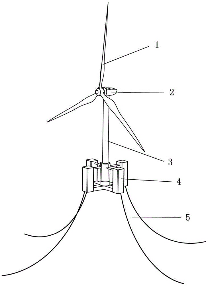
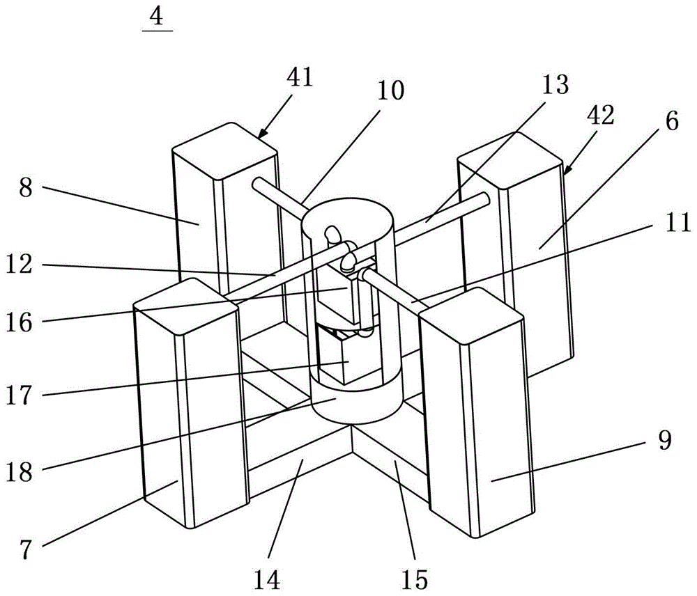
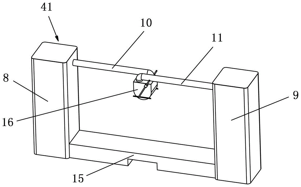
[0066] figure 1 is a perspective view illustrating an offshore wind power generator according to an embodiment of the present disclosure. Such as figure 1 As shown, the offshore wind generator mainly includes: a floating foundation 4; a plurality of mooring cables 5, one end of which is connected to the floating foundation 4, and the other end is anchored on the seabed; a tower 3 is installed on the floating foundation 4 and is supported by the floating foundation 4 Support; the wind power generating set 2 and the blade 1 are installed on the top of the tower 3 . The bottom end of the tower 3 can be connected to the floating foundation 4 through a tower supporting device, in the present disclosure, the tower supporting device is a supporting column 18 arranged in the center of the floating foundation 4 (details will be described below).

[0067] figure 2...


PUM


Abstract

The invention discloses a stabilizing device, a floating foundation and an offshore wind power generator. The stabilizing device comprises a U-shaped water chamber, wherein the U-shaped water chamber comprises a first hollow upright column, a second hollow upright column and a bottom buoyancy tank connected between the bottoms of the two upright columns, the first upright column and the second upright columns are communicated with the bottom buoyancy tank, and the top of the first upright column and the top of the second upright column are communicated through an air communication pipeline. The floating foundation is at least provided with a first upright column, a second upright column and a third upright column, and comprises at least one stabilizing device. The offshore wind power generator comprises the floating foundation, a mooring rope, a tower, vanes and a wind power generator set, wherein the mooring rope is connected with the outer edge of the floating foundation and is anchored to the seabed, the bottom end of the tower is arranged on the floating foundation, and the vanes and the wind power generator set are arranged on the top of the tower. By means of the stabilizing device, stabilizing of a floating fan can be simply and effectively achieved through a double-resonance principle.

Description

technical field [0001] The present disclosure relates to an offshore wind power generator, and more particularly, to an anti-rolling device and a floating foundation with the anti-rolling device. Background technique [0002] At present, in order to meet the needs of developing deep-sea wind farms, people have applied the deep-sea floating oil platform commonly used in the offshore oil industry to the wind power field, and successively developed single-pillar platforms (SPAR), semi-submersible platforms (Semi-submersible), tension Leg platform (TLP) floating fans and other composite floating fans. So far, three floating wind turbine projects have been built, such as figure 1 Shown are Hywind, Blue H and Windfloat respectively. Hywind was jointly developed by Statoil Hydro of Norway, Technip of France and Siemens of Germany, and was built in the North Sea near Norway in 2009. The basic concept adopted by Hywind is SPAR. The floating structure is a slender steel pipe about ...

Claims


Application Information

Patent Timeline
Patent Type & Authority Patents(China)
IPC IPC(8): B63B35/00F03D9/30F03D1/00
CPCB63B1/107B63B39/03B63B2001/128B63B2035/446
Inventor 李荣富张建海朱海飞张新刚
Owner XINJIANG GOLDWIND SCI & TECH CO LTD
Why Eureka
Eureka Blog
Learn More