
Automobile air-conditioning system

A technology of automotive air conditioning system and air conditioning box, which is applied in the direction of air conditioning system, space heating and ventilation, space heating and ventilation details, etc. It can solve the problems of affecting the comfort of passengers, shortening the mileage of the use of heat-generating components, and difficult layout.

Active Publication Date: 2014-04-09
HANGZHOU SANHUA RES INST CO LTD
View PDF5 Cites 9 Cited by
  • Summary
  • Abstract
  • Description
  • Claims
  • Application Information

AI Technical Summary

Problems solved by technology

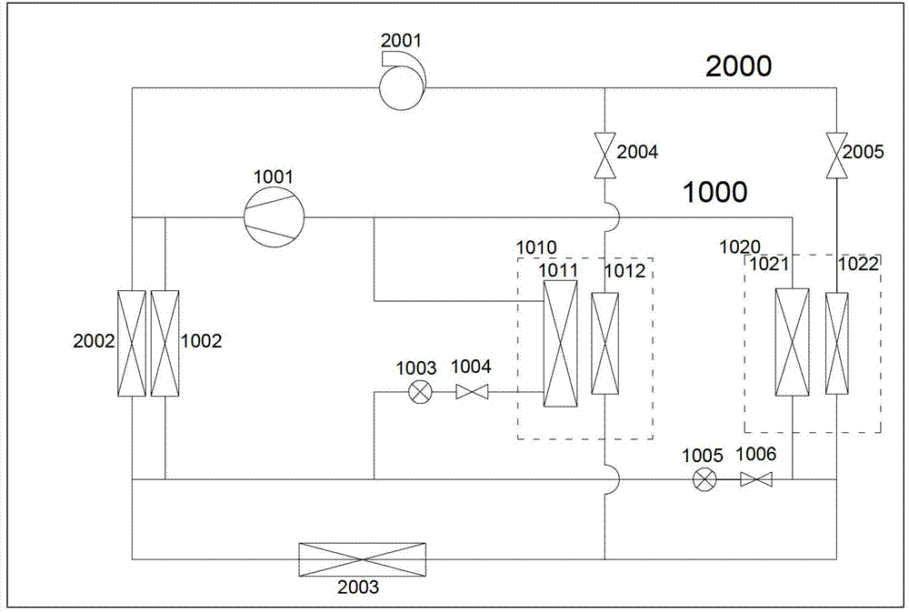
[0006] Third, this contradiction is particularly prominent in areas with relatively harsh environments, such as areas with high and cold winters
During these heat exchanges, there will definitely be heat loss, so the efficiency must be less than 1
[0013] 4) In addition, when heating, because the specific heat of the working fluid in the cycle 2000 is relatively large, and the power of the electric heater is limited, the temperature rise of the working fluid in the cycle 2000 is relatively slow, and the temperature rise of the air is also slow. This will affect the comfort of passengers
[0014] 5) Since the temperature of the battery and other heat-generating components is relatively low when the battery is just started, the temperature rises slowly, which will affect the performance of the battery and other heat-generating components (such as shortened mileage and shortened service life)
[0015] 6) In addition, the system has both refrigeration cycle and heating cycle of working fluid and heating cycle of 2000 working fluid. The system has many parts and is relatively complicated. It is difficult to arrange on the vehicle and the manufacturing cost is high.

Method used


Image

  • Automobile air-conditioning system
  • Automobile air-conditioning system
  • Automobile air-conditioning system

Examples


Embodiment Construction

[0095] The core of the present invention is to provide an automobile air-conditioning system, which can significantly improve the efficiency of the compressor and the air-conditioning system, and ensure the demand for heat in the cold environment, thereby ensuring the comfort of passengers and the stable and efficient operation of heating components.

[0096] In order to enable those skilled in the art to better understand the technical solutions of the present invention, the present invention will be further described in detail below in conjunction with the accompanying drawings and specific embodiments.

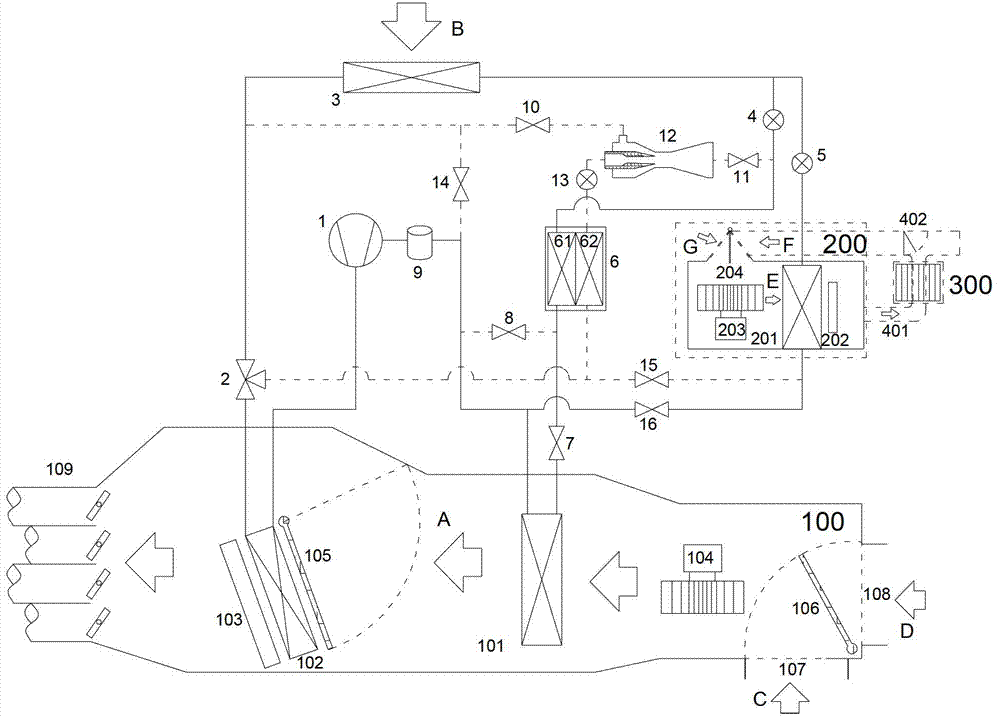
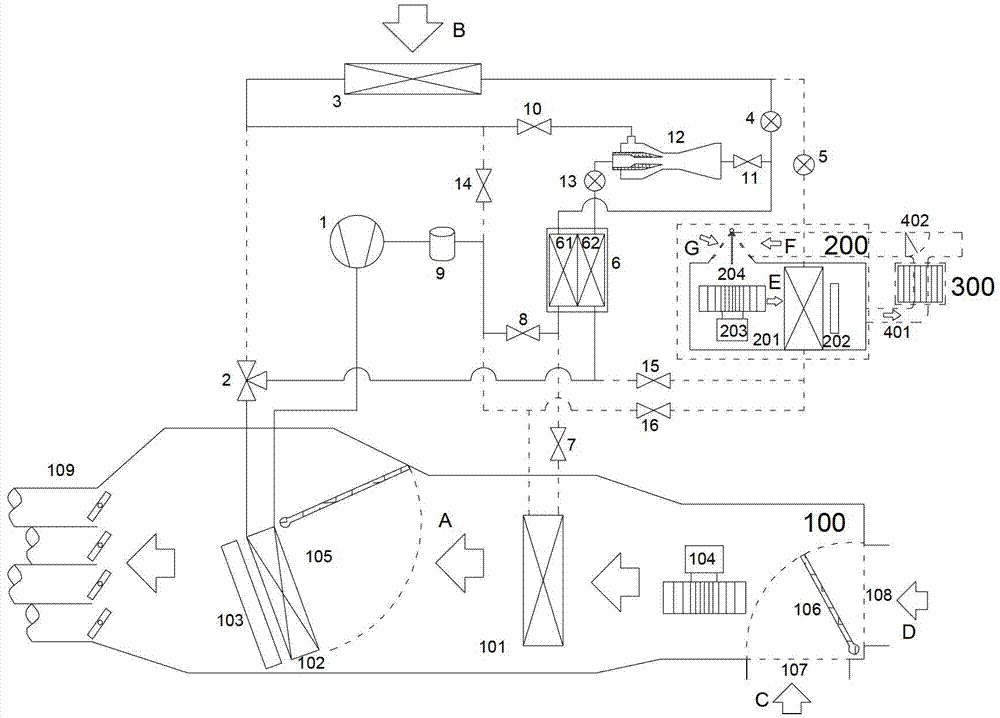
[0097] Please refer to Figure 2 to Figure 5 , first of all, it needs to be explained that in the drawings with dotted lines in this article, it involves the pipeline through which the working fluid passes. conduction or selectable conduction. The conduction or interruption of the working medium on the pipeline is realized through the control of the corresponding stop valv...


PUM


Abstract

The invention discloses an automobile air-conditioning system. The automobile air-conditioning system further comprises an ejector (12) and an intermediate heat exchanger (6). In a heating mode, a working medium flowing from an outlet of a second heat exchange (102) is divided into a first channel and a second channel; the first channel of the working medium flows into the ejector (12) through a drive inlet after flowing out of a high-temperature side (62), and then is divided into a first branch and a second branch after being ejected from an outlet of the ejector (12), the first branch of the working medium flows back into a compressor (1) through a low-temperature side (61), and the second branch of the working medium flows into the ejector (12) through a bypass guide hole via a third heat exchanger (3). The automobile air-conditioning system has the advantages that efficiency of the compressor and the air-conditioning system can be improved effectively, requirements for heat in high and cold environment can be guaranteed, and comfortableness of passengers and stable and efficient performance of heating components are guaranteed.

Description

technical field [0001] The invention relates to the technical field of automobile air-conditioning, in particular to an air-conditioning system for an electric vehicle or an air-conditioning system for a hybrid vehicle. Background technique [0002] With the development of low-carbon economy, more stringent requirements are put forward for energy saving and emission reduction. All countries in the world regard new energy vehicles as the strategic direction of the development of the automobile industry, and electric vehicles or hybrid vehicles are becoming the future due to their energy-saving and environmental protection features. One of the aspects of automobile development. However, because electric vehicles use batteries as the power source and batteries as the core components, their cost and capacity / weight restrict the development of new energy vehicles; their air-conditioning systems are also different from the original automotive air-conditioning systems. Traditional...

Claims


Application Information

Patent Timeline
Patent Type & Authority Applications(China)
IPC IPC(8): F24F1/00F24F13/30F25B9/08F25B41/04F25B41/20
Inventor 黄宁杰刘维华董洪洲王艳红
Owner HANGZHOU SANHUA RES INST CO LTD
Learn More