Spectrometer and working method

A working method and spectrometer technology, applied in the field of spectral analysis, can solve the problems of increasing the volume and cost of spectrometers, and achieve the effects of low cost, reduced range requirements, and high-resolution spectral detection

Active Publication Date: 2016-04-27
FOCUSED PHOTONICS
View PDF3 Cites 0 Cited by
  • Summary
  • Abstract
  • Description
  • Claims
  • Application Information

AI Technical Summary

Problems solved by technology

[0003] The classic Michelson interferometer can only provide an optical path difference twice the moving distance of the moving mirror, so the Fourier transform infrared spectrometer based on the classical Michelson interferometer must increase the moving range of the moving mirror in order to obtain high-resolution spectra , a voice coil motor or linear motor with a large stroke is required, which will increase the size and cost of the spectrometer

Method used


Image

  • Spectrometer and working method
  • Spectrometer and working method

Examples


Embodiment 1

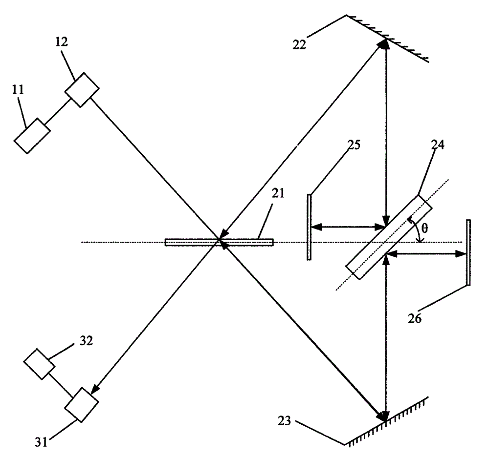
[0040] figure 1 The structural diagram of the spectrometer of the embodiment of the present invention is schematically provided, as figure 1 As shown, the spectrometer includes:

[0041] A light source 11 and a detector 32. The light source 11 and the detector 32 are prior art in the art, and will not be repeated here;

[0042] A beam splitter 21, the beam splitter 21 is arranged on the optical path of the measurement light emitted by the light source 11, and is used to split the measurement light into a first beam and a second beam;

[0043] A first reflection unit 22, the first reflection unit 22 is used to reflect the first light beam to a third reflection unit 24;

[0044] A second reflection unit 23, the second reflection unit 23 is used to reflect the second light beam to the third reflection unit 24;

[0045] The third reflection unit 24, one side of the third reflection unit 24 reflects the first light beam to the fourth reflection unit 25, and the other side reflec...

Embodiment 2

[0063] An application example of the spectrometer and working method in gas detection according to Embodiment 1 of the present invention. Specifically detect the content of gases such as carbon dioxide.

[0064] Such as figure 1 As shown, in this application example, the infrared light beam emitted by the infrared light source 11 is collimated by the parabolic reflector 12, and the collimated light beam is split by the beam splitter 21 (two beams of reflected and transmitted light); The two beams of light behind the beam are incident on the double-sided (parallel) reflective plate 24 in the direction perpendicular to the plane where the beam splitter 21 is located through the plane reflector 22 and the plane reflector 23 respectively; the reflector 22 and the reflector 23 are symmetrical about the beam splitter 21 Set, the two infrared light beams reflected by the two sides of the double-sided reflective plate 24 are retroreflected through the plane reflector 25 and the plane...

Embodiment 3

[0067] An application example of the spectrometer and working method in gas detection according to Embodiment 1 of the present invention. Specifically detect the content of gases such as carbon monoxide.

[0068] Such as figure 1 As shown, in this application example, the infrared light beam emitted by the infrared light source 11 is collimated by the parabolic reflector 12, and the collimated light beam is split by the beam splitter 21 (two beams of reflected and transmitted light); The two beams of light behind the beam are incident on the double-sided (parallel) reflective plate 24 in the direction perpendicular to the plane where the beam splitter 21 is located through the plane reflector 22 and the plane reflector 23 respectively; the reflector 22 and the reflector 23 are symmetrical about the beam splitter 21 Set, the two infrared light beams reflected by the two sides of the double-sided reflective plate 24 are retroreflected through the plane reflector 25 and the plan...


PUM


Abstract

The invention provides a spectrograph and a working method. The spectrograph comprises a light source and a detector. The spectrograph further comprises a beam splitter, a first reflection unit, a second reflection unit, a third reflection unit, a fourth reflection unit, a fifth reflection unit and a motion mechanism. The beam splitter is arranged on a light path of measuring light emitted by the light source so as to divide the measuring light into a first light beam and a second light beam; the first reflection unit reflects the first light beam to the third reflection unit; the second reflection unit reflects the second light beam to the third reflection unit; one lateral face of the third reflection unit reflects the first light beam to the fourth reflection unit and the other lateral face of the third reflection unit reflects the second light beam to the fifth reflection unit; the included angle between the reflection face of the third reflection unit and the reflection face of the beam splitter is an acute angle; the fourth reflection unit reflects the first light beam to enable the first light beam to return to the beam splitter along the original path and enter the detector; the fifth reflection unit is used for reflecting the second light beam to enable the second light beam to return to the beam splitter along the original path and enter the detector; the motion mechanism is used for moving the third reflection unit horizontally and / or rotating the third reflection unit. The spectrograph has the advantages of being simple in structure, high in resolution ratio, low in cost and the like.

Description

technical field [0001] The invention relates to spectral analysis, in particular to a spectrometer and a working method. Background technique [0002] The basic principle of the Fourier transform infrared spectrometer is: the collimated infrared beam enters the interferometer, and the interferogram under different optical path differences is obtained through the movement of the moving mirror in the interferometer. The function of the path difference change, the obtained interferogram is Fourier transformed, and the corresponding spectrum can be obtained, so as to realize the spectrum detection. The interferometer is the core component of the Fourier transform infrared spectrometer. The optical path difference provided by the interferometer directly determines the resolution of the spectrometer. [0003] The classic Michelson interferometer can only provide an optical path difference twice the moving distance of the moving mirror, so the Fourier transform infrared spectrome...

Claims


Application Information

Patent Timeline
Patent Type & Authority Patents(China)
IPC IPC(8): G01J3/45G01J3/02
Inventor 华道柱张良黄伟叶华俊
Owner FOCUSED PHOTONICS
Why Eureka
Try Eureka