Honeycombed laser scanning method for selective laser sintering

A laser sintering and laser scanning technology, which is applied in the field of additive manufacturing, can solve problems such as cracks and warpage of formed layers, and achieve the effects of improving dimensional accuracy, reducing workpiece deformation, and simple control

Inactive Publication Date: 2014-04-16
HEFEI UNIV OF TECH
View PDF5 Cites 22 Cited by
  • Summary
  • Abstract
  • Description
  • Claims
  • Application Information

AI Technical Summary

Problems solved by technology

When this stress is severe, it will lead to warping and deformation of the formed layer, and when it...

Method used


Image

  • Honeycombed laser scanning method for selective laser sintering
  • Honeycombed laser scanning method for selective laser sintering
  • Honeycombed laser scanning method for selective laser sintering

Examples


specific Embodiment

[0039] A honeycomb laser scanning method for selective laser sintering, mainly comprising steps:

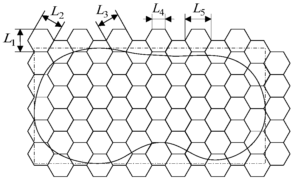
[0040] S1. According to the bounding box of the cross-sectional outline of the digital model of the part, a regular hexagonal regular arrangement and combination template is obtained, and the boundary line of the template is required to be completely outside the bounding box, such as figure 1 shown.

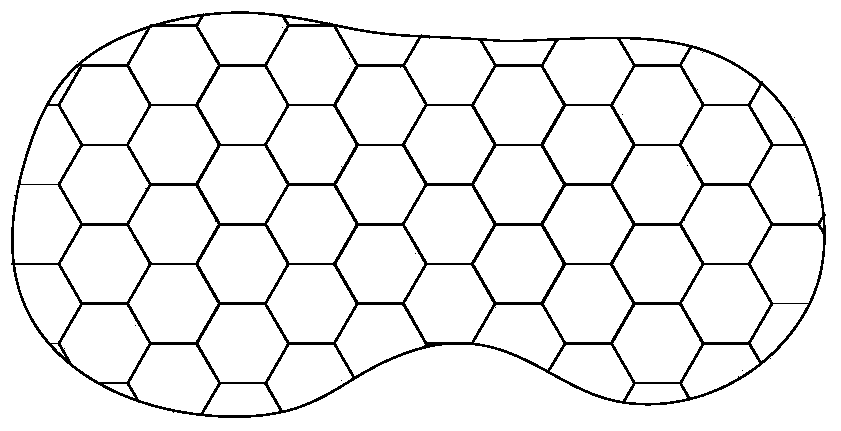
[0041] S2. Use the cross-sectional outline of the digital model of the part to cut the template, and obtain the template part located inside the outline, that is, the overall scanning path, such as figure 2 shown.

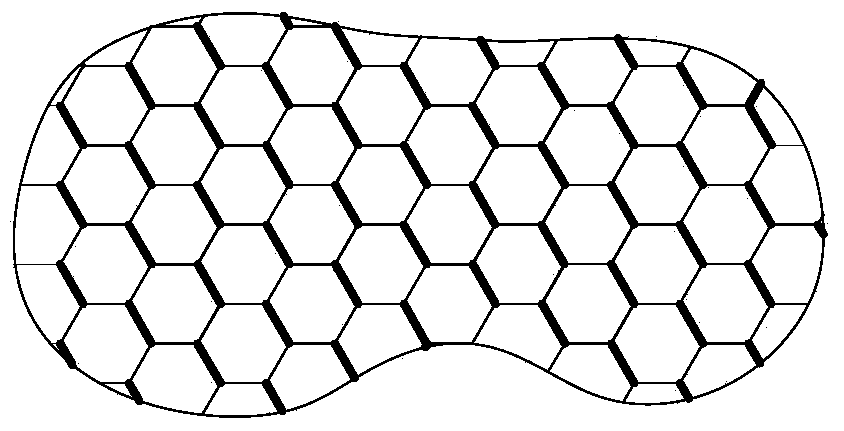
[0042] S3. According to the overall scanning path, the computer controls the laser beam to perform intermittent scanning along the direction of 120° with the x-axis to generate a series of intermittent scanning trajectories at 120° with the x-axis, such as image 3shown. The normal length of a regular line segment is 1 / 2 of its interval, namely L 4 =0.5L 5 , L 4 i...


PUM


Abstract

The invention discloses a honeycombed laser scanning method for selective laser sintering. The method includes: calculating laser scanning paths within a section profile according to information of the section profile, and enabling laser beams to scan metal powder of solid portions of workpieces according to the scanning paths under the control of a computer to directly manufacture the workpieces. Three groups of intermittent linear scanning paths in parallel form a honeycombed integrated path finally. The honeycombed laser scanning method is simple in technical control and high in practicality, strength of the workpieces can be improved, deformation of the workpieces can be reduced, and dimensional precision of the workpieces can be improved.

Description

technical field [0001] The invention relates to the field of additive manufacturing, in particular to a honeycomb laser scanning method for selective laser sintering. Background technique [0002] Additive Manufacturing, also known as rapid prototyping or rapid prototyping (RP for short), is a manufacturing technology that rapidly generates parts or models, integrating numerical control technology, mechanical design and manufacturing, new material technology and computer Applied technology is the product of multidisciplinary integration. Additive manufacturing is commonly known as 3D printing. [0003] The Selective Laser Sintering (SLS) process was successfully developed by Dr. Carl Dechard and his mentor Dr. Joe Beaman at the University of Texas at Austin in the mid-1880s and commercialized. The SLS process uses powdered materials to form: (1) Spread the material powder on the upper surface of the formed part and scrape it flat; (2) Use a high-intensity CO2 laser to scan...

Claims


Application Information

Patent Timeline
IPC IPC(8): B22F3/105
CPCY02P10/25
Inventor 李维诗张振于连栋夏豪杰
Owner HEFEI UNIV OF TECH
Why Eureka
Try Eureka