A hydraulic brake system

A technology of hydraulic brake and frame, applied in the field of hydraulic brake system, can solve the problems of serious tire wear and braking distance, easy twisting of the handle, inconvenient use, etc. Effect

Active Publication Date: 2016-05-11
江苏众力合创精密机械科技有限公司
View PDF8 Cites 2 Cited by
  • Summary
  • Abstract
  • Description
  • Claims
  • Application Information

AI Technical Summary

Problems solved by technology

[0002] The existing battery car and motorcycle braking devices are all braked at one time. This braking method is easy to cause serious tire wear and long braking distance, and the handle is easy to twist to cause tail flicking. Sometimes it is often necessary to manually slowly reciprocate the pull cable to brake the braking device multiple times, which is cumbersome to operate, inconvenient to use, and poor in safety. For example, "a kind of brake" disclosed by the authorization announcement number CN201647041U refers specifically to a kind of brake for battery cars. Or the brake on the motorcycle, a brake shoe block assembly is arranged on the inner side of the drum cover. The brake shoe block assembly is composed of two symmetrically arranged semicircle-arc brake shoe blocks. The adjacent ends of the two brake shoe blocks pass through the semicircle The groove is clamped with the cylinder fixed on the drum cover, a cam is set between the other ends of the two brake shoes, and a return spring for tensioning it is arranged between the two brake shoes. There is a cam rocker arm assembly and a brake line support. The rocker arm of the cam rocker arm assembly is fixedly connected to the cam through a rotating shaft. A torsion spring is arranged between the rocker arm and the drum cover to make the cam rotate. One end of the torsion spring is stuck on the drum cover. , the other end is set on the rocker arm

Method used


Image

  • A hydraulic brake system
  • A hydraulic brake system
  • A hydraulic brake system

Examples


Embodiment

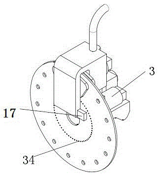
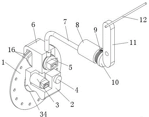
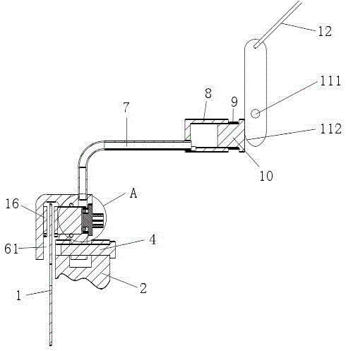
[0036] A hydraulic brake system, comprising a brake disc 1, a brake mechanism for braking the brake disc 1, and a drive mechanism for driving the brake mechanism, the drive mechanism includes a cable 12, a drive rocker arm 11 And the pressure oil cylinder 8, the upper end of the driving rocker arm 11 is connected with the drag cable 12, the lower end side is against the pressure piston 10 of the pressure oil cylinder 8, and the lower end side of the driving rocker arm is against the rear end of the pressure piston. The brake mechanism includes a brake caliper body 6 fixed on the vehicle frame 2, a friction plate 16 arranged on the brake caliper body 6, a mechanism for driving the friction plate 16 arranged in the brake caliper body 6 The hydraulic cylinder and the electromagnet 5 used to control the reciprocating movement of the brake piston 15 in the brake cylinder and the trigger device used to control the power on and off of the electromagnet, the pressure cylinder 8 is conn...


PUM


Abstract

The invention belongs to the technical field of a brake, and particularly relates to a hydraulic braking system used for a storage battery car, a motorcycle and a bicycle with relatively high speed. The hydraulic braking system comprises a braking plate, a braking mechanism and a driving mechanism, wherein the driving mechanism comprises a pull rope, a driving rocker arm and a pressure oil cylinder; the upper end of the driving rocker arm is connected with the pull rope, and one side of the lower end of the driving rocker arm is abutted against a pressure piston of a pressure oil cylinder; the braking mechanism comprises a braking clamp body fixedly arranged on a car frame, a friction sheet arranged on the braking clamp body, a braking oil cylinder arranged inside the braking clamp body and used for driving the friction sheet, an electromagnet used for controlling the braking piston inside the braking oil cylinder to do reciprocating motion, and a triggering device used for controlling the electromagnet to be switched on and off; the pressure oil cylinder is communicated with an oil cavity of the braking oil cylinder through an oil pipe. The hydraulic braking system provided by the invention can be used for repeatedly clamping and releasing for multiple times by pulling the pull rope again and again, so that the braking distance is reduced, and the driving security is improved on the premise of reducing the labor intensity of operators.

Description

technical field [0001] The invention belongs to the technical field of brakes, in particular to a hydraulic brake system for battery cars, motorcycles and fast bicycles. Background technique [0002] The existing battery car and motorcycle braking devices are all braked at one time. This braking method is easy to cause serious tire wear and long braking distance, and the handle is easy to twist to cause tail flicking. Sometimes it is often necessary to manually slowly reciprocate the pull cable to brake the braking device multiple times, which is cumbersome to operate, inconvenient to use, and poor in safety. For example, "a kind of brake" disclosed by the authorization announcement number CN201647041U refers specifically to a kind of brake for battery cars. Or the brake on the motorcycle, a brake shoe block assembly is arranged on the inner side of the drum cover. The brake shoe block assembly is composed of two symmetrically arranged semicircle-arc brake shoe blocks. The a...

Claims


Application Information

Patent Timeline
Patent Type & Authority Patents(China)
IPC IPC(8): F16D65/14B62L1/02B60T1/02F16D121/04F16D121/20
Inventor 严峥源周忠友
Owner 江苏众力合创精密机械科技有限公司
Why Eureka
Try Eureka