
Gas analyzer

一种气体分析、气体的技术,应用在测量装置、分析材料、通过光学手段进行材料分析等方向,能够解决高温、易老化、分析装置大型化等问题,达到分析精度良好、降低制造成本的效果

Active Publication Date: 2014-04-16
HORIBA LTD
View PDF8 Cites 7 Cited by
  • Summary
  • Abstract
  • Description
  • Claims
  • Application Information

AI Technical Summary

Problems solved by technology

Therefore, there is a problem that accurate zero-point correction cannot be performed, and high-precision component analysis is difficult.
In addition, since a separate system (a system consisting of a light receiving unit and a signal processing circuit) is required to process the split beams separately, the entire analysis device is enlarged
In addition, there is a problem that the heat generated by the entire analysis device increases due to the heat generated by each system, and the durability of the signal processing response is reduced.
The gas analysis device of the probe type is installed on the chimney, etc., and it is easily affected by the heat of the sample gas and becomes high temperature, so it is particularly prone to aging

Method used


Image

  • Gas analyzer
  • Gas analyzer
  • Gas analyzer

Examples


no. 1 approach )

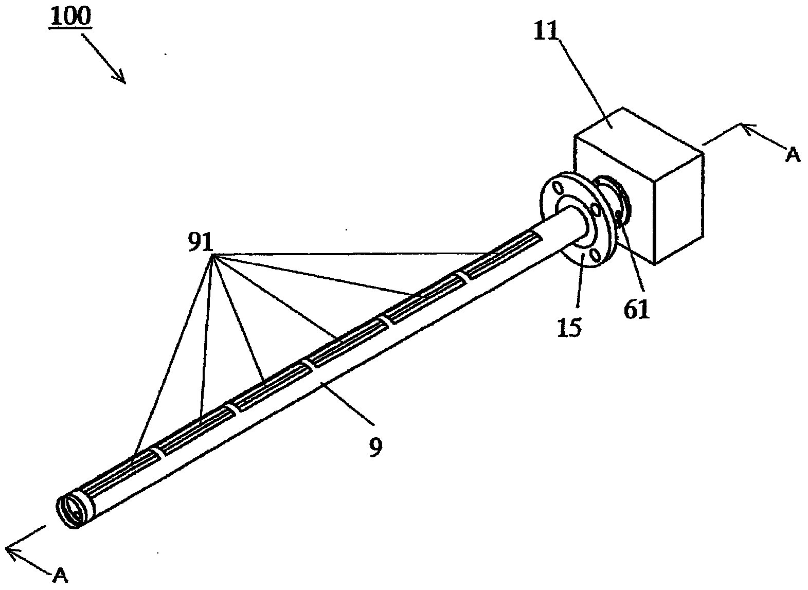
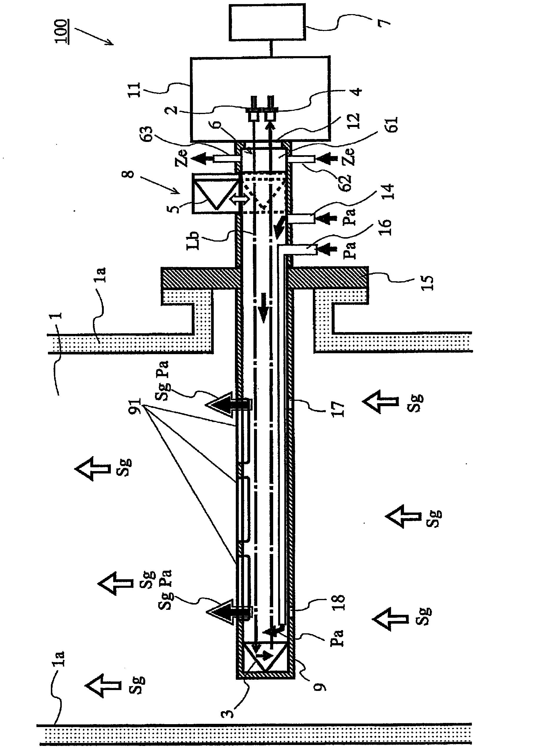
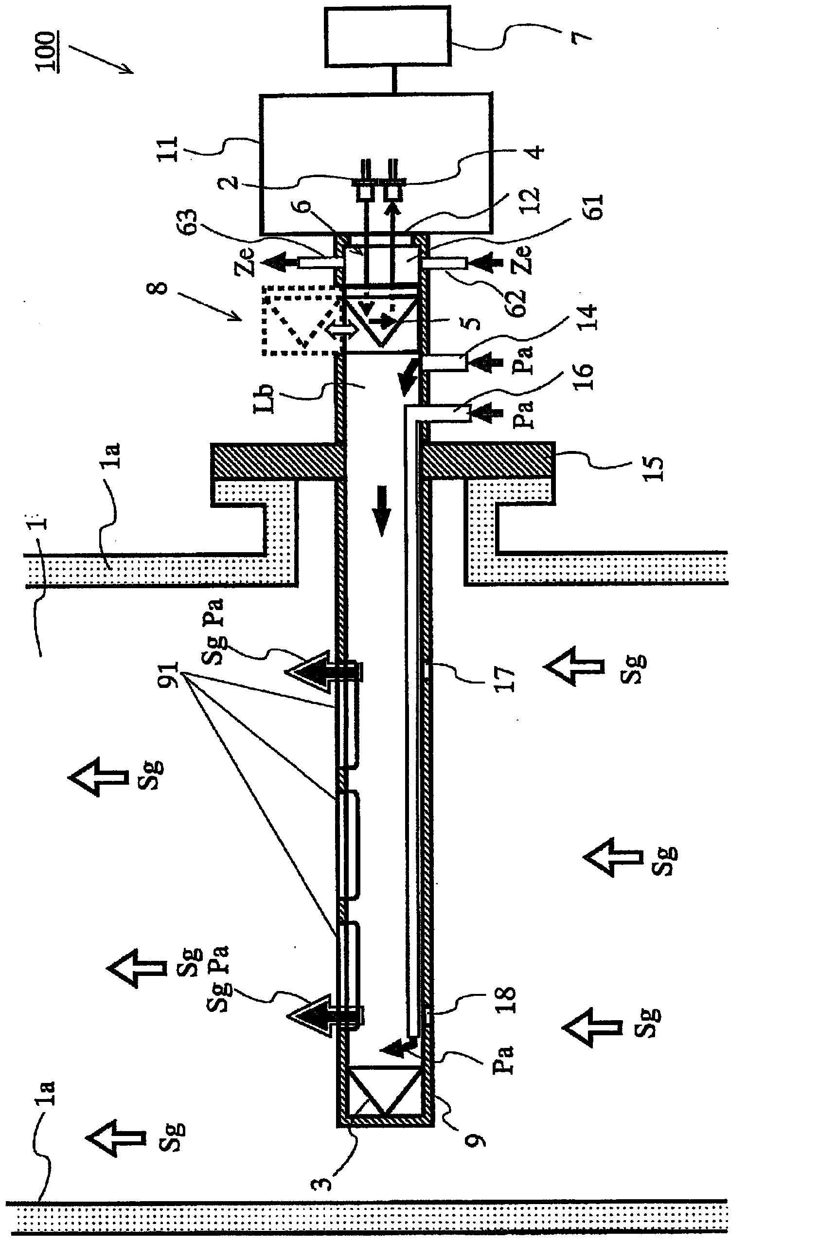
[0086] Next, the gas analysis device 100 of the first embodiment will be described. The gas analysis device 100 is a so-called probe type gas analysis device. figure 1 It is an external configuration diagram of the gas analysis device of the first embodiment. figure 2 Yes figure 1 The diagram including the A-A section of the gas analysis device shown is a diagram showing a gas concentration analysis mode. image 3 Yes figure 1 The figure including the A-A cross section of the shown gas analysis device is a figure showing a correction mode or a calibration mode.

[0087] The gas analysis device 100 of the first embodiment is a gas analysis device for analyzing the concentration of a predetermined component in a sample gas flowing through the flue 1 . The gas analysis device 100 is, for example, a non-dispersive infrared analyzer (Non-dispersive Infrared Analyzer: NDIR).

[0088] like figure 2 , image 3 As shown, the gas analysis device 100 includes: an irradiation uni...

no. 2 approach )

[0130] Next, the gas analysis device 200 of the second embodiment will be described. The gas analysis device 200 is a so-called open hole type gas analysis device. Figure 8 It is a sectional view showing the internal structure of the gas analysis device according to the second embodiment, and is a view showing a gas concentration analysis mode. Figure 9 It is a sectional view showing the internal structure of the gas analysis device according to the second embodiment, and is a view showing a zero point correction mode. The difference between the second embodiment and the first embodiment will be mainly described, and the same reference numerals will be assigned to the same structures as those of the first embodiment, and descriptions thereof will be omitted.

[0131] In the second embodiment, as Figure 8 , Figure 9 As shown, the gas analysis device 200 is composed of a first unit 19 and a second unit 20 formed in a separate body. The first unit 19 is installed on one s...

no. 3 approach )

[0145] use Figure 10 ~ Figure 13 A third embodiment will be described. The third embodiment differs from the embodiment only in the structure supporting the second mirror 5 . Figure 10 It is a sectional view showing the structure of the switching unit of the third embodiment, and is a view showing a correction mode or a calibration mode. Figure 11 is a perspective view of a bearing. Figure 12 is a top view of the bearing. Figure 13 Yes Figure 10 A partial enlargement of the .

[0146] The second mirror 5 is held by the mirror holder 104 .

[0147] like Figure 10As shown, in the above embodiment, the forward and backward moving mechanism has a positioning mechanism 101, and when the cylinder 84 returns the second reflecting mirror 5 to the optical path, the positioning mechanism 101 is used to make the second reflecting mirror 5 always face the same direction and It is positioned at the same location.

[0148] The positioning mechanism 101 is disposed below the s...


PUM


Abstract

The invention provides a gas analyzer. The gas analyzer (100) is provided with: an irradiation unit (2) arranged on the outside of a flue wall (1a); a first reflector (3) for reflecting measurement light that has passed through a sample gas (Sg) emitted from the irradiation unit (2); a light-receiving unit (4) arranged on the outside of the flue wall (1a) and adapted for receiving the measurement light reflected by the first reflector (3); a second reflector (5) arranged on the outside of the flue wall (1a) and adapted for reflecting the measurement light toward the light-receiving unit (4); a known-substance-accommodating unit (6) for accommodating a known substance, the unit being provided in a space on an optical path between the irradiation unit (2) and the second reflector (5); a calculation unit (7) for reflecting the measurement light emitted from the irradiation unit (2) using the first reflector (3) and analyzing the sample gas (Sg), reflecting the measurement light emitted from the irradiation unit (2) using the second reflector (5), and performing compensation or calibration using the known substance of the gas analyzer (100); and a switching unit (8) arranged on the outside of the flue wall (1a), and adapted for removing the second reflector (5) from the optical path when analyzing component concentration, and arranging the second reflector (5) on the optical path when performing compensation or calibration.

Description

technical field [0001] The present invention relates to a gas analysis device, in particular to a gas analysis device for specific analysis of the concentration of specified components in a sample gas by using light absorption method. Background technique [0002] Conventionally, NOx, Sox, CO 2 , CO and other components. Furthermore, a gas analysis device for analyzing the content of the above-mentioned components in gas has been developed. As such a gas analysis device, for example, a device using a probe system has been developed. A probe-type gas analysis device reflects measurement light emitted from a light source by a reflection mirror arranged at the tip of the probe, and analyzes the component concentration of a sample gas based on information on the measurement light reflected by the reflection mirror. [0003] In some conventional gas analyzers of the probe type, a zero point correction function is provided in addition to the component concentration analysis fun...

Claims


Application Information

Patent Timeline
Patent Type & Authority Applications(China)
IPC IPC(8): G01N21/61G01N21/39
CPCG01N21/274G01N2021/536G01N21/3504G01N2021/8514G01N2021/8578G01N2021/3513G01N21/61
Inventor 井户琢也大西敏和森哲也
Owner HORIBA LTD
Learn More