A kind of metal shell soldering method

A metal shell and soldering technology, used in metal processing, metal processing equipment, welding equipment, etc., can solve the problems of affecting product performance, the inability of double-sided printed boards, and the inability to guarantee the number of peripheral screws, and achieve good grounding. effect, the effect of good impact resistance reliability

Active Publication Date: 2016-01-13
CHENGDU SINE SCI & TECH
View PDF6 Cites 2 Cited by
  • Summary
  • Abstract
  • Description
  • Claims
  • Application Information

AI Technical Summary

Problems solved by technology

[0004] 1) In order to ensure that the printed board can be fixed in the metal shell during the design process of the printed board, it is necessary to reserve screw mounting holes in the printed board, which directly increases the printed board area of ​​the product, such as in the printed board area The fixed situation will bring certain difficulties to the designer in terms of layout, and the product often has certain difficulties in the process of fixing
[0005] 2) When fixing a printed board with a large area, there are a certain number of screw holes on the printed board, so the screw hole installation method can play a certain role in the anti-vibration and impact ability of the product in such cases; and Due to the requirements of product design and layout for small-area printed boards, it is often impossible to reserve screw holes in the middle and the number of peripheral screws cannot be guaranteed, and the screws used for fixing are often small-sized screws. There are often limitations in testing
[0006] 3) RF and microwave products often require a reliable grounding effect, and poor grounding effect often affects product performance
[0008] Using reflow soldering combined with solder paste to fix the printed board inside the metal shell is only suitable for single-sided printed boards. Some printed boards for RF and microwave products often need to be designed as two-sided boards to save product space. For double-sided printed boards The fastening of the plate to the metal case is often impotent

Method used


Image

  • A kind of metal shell soldering method
  • A kind of metal shell soldering method
  • A kind of metal shell soldering method

Examples


Embodiment Construction

[0039] The present invention will be further described below in conjunction with the accompanying drawings.

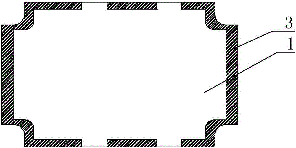
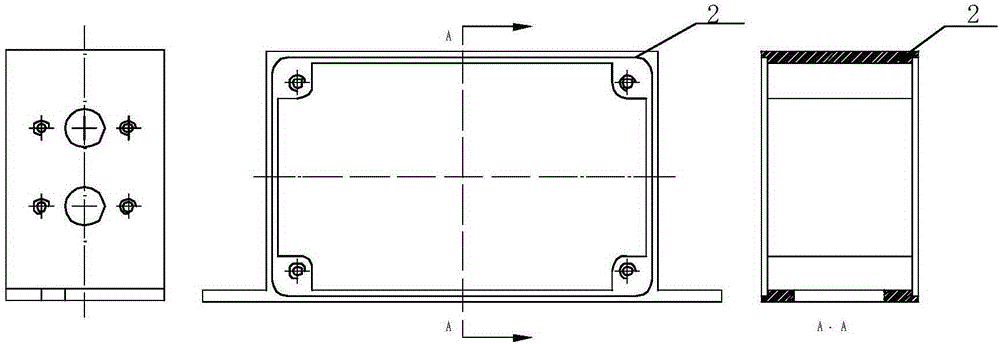
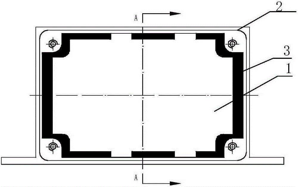
[0040] As shown in the accompanying drawings, a metal shell soldering method is:

[0041] Step 1: Fixing, position the printed board 1 in the metal shell 2, and initially fix the printed board 1 and the metal shell 2 with solder; there are grounding holes around the printed board;

[0042] Step 2: Preheat

[0043] Place the fixed printed board and metal shell on a temperature-controlled heating table for preheating. The preheating temperature is between 130°C and 180°C, and the preheating time is not less than 3 minutes.

[0044] Step 3: Apply Rosin Flux

[0045] Apply rosin flux to the solder joints;

[0046] Step 4: Soldering

[0047] Adjust the temperature-adjustable soldering iron to 300°C to 380°C, wipe the tip of the soldering iron with wet foam cotton, and apply an appropriate amount of solder (until the solder does not fall off), the tip of the soldering ir...


PUM


Abstract

The invention discloses a metal shell soldering method which includes the steps of (1) fixing, wherein a printing plate is located in a box, and the printing plate to be welded can not move relative to the box; (2) preheating, wherein the positioned and fixed printing plate and the box are arranged on a temperature control heating table for preheating, preheating temperature ranges from 130 DEG C to 180 DEG C, and preheating time is not shorter than 3 minutes; (3) soldering flux coating; (4) welding; (5) cleaning. After the printing plate and the box are welded by means of the metal shell soldering method, the printing plate and the box can form a seamless integrated structure, so that a product has better impact resistance and reliability. Besides, screws are not designed in product design for fixing, so that space of the product in the design process is saved, and the size of the whole product is smaller. Due to the fact that the double-face printing plate and the box are welded in a large area by means of solder, a good grounding effect of the product can be guaranteed.

Description

technical field [0001] The invention relates to a welding method, in particular to a soldering method of a printed board and a shielding metal shell. Background technique [0002] Most of the existing methods for fixing printed boards of radio frequency and microwave products use screws or reflow soldering combined with solder paste to fix single-sided printed boards in metal shells. [0003] The screw fixing method first reserves screws on the printed board, and fixes it to the metal shell with screws during the installation process. Using this kind of screw to fix the RF microwave printed board will cause the following problems: [0004] 1) In order to ensure that the printed board can be fixed in the metal shell during the design process of the printed board, it is necessary to reserve screw mounting holes in the printed board, which directly increases the printed board area of ​​the product, such as in the printed board area The fixed situation will bring certain diffi...

Claims


Application Information

Patent Timeline
Patent Type & Authority Patents(China)
IPC IPC(8): B23K1/00B23K1/20B23K1/14
CPCB23K1/0008B23K1/08B23K1/20B23K37/06B23K2101/42
Inventor 姚宗诚易增辉谭奇
Owner CHENGDU SINE SCI & TECH
Why Eureka
Try Eureka