Printing head sprayer structure of 3D (3-dimensional) printer

A 3D printer and print head technology, applied in the field of printing equipment, can solve the problems of low filament discharge efficiency of nozzles, difficult extrusion of consumables, and easy blocking of nozzles, so as to achieve the effect of low resistance, easy extrusion of consumables, and difficulty in blocking.

Inactive Publication Date: 2014-04-23
德清中科金融信息技术研究所
View PDF6 Cites 23 Cited by
  • Summary
  • Abstract
  • Description
  • Claims
  • Application Information

AI Technical Summary

Problems solved by technology

[0006] The purpose of the present invention is to address the above problems, to provide a print head nozzle structure of a 3D printer, which solves the technical pro

Method used


Image

  • Printing head sprayer structure of 3D (3-dimensional) printer
  • Printing head sprayer structure of 3D (3-dimensional) printer
  • Printing head sprayer structure of 3D (3-dimensional) printer

Examples


Embodiment Construction

[0022] The present invention will be described in further detail below in conjunction with the accompanying drawings and specific embodiments.

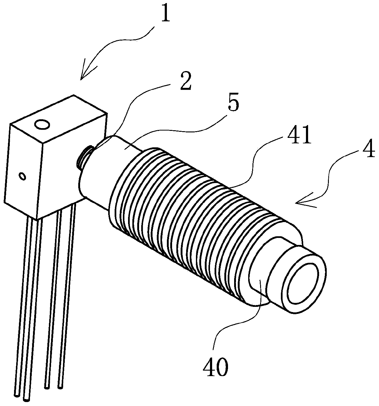
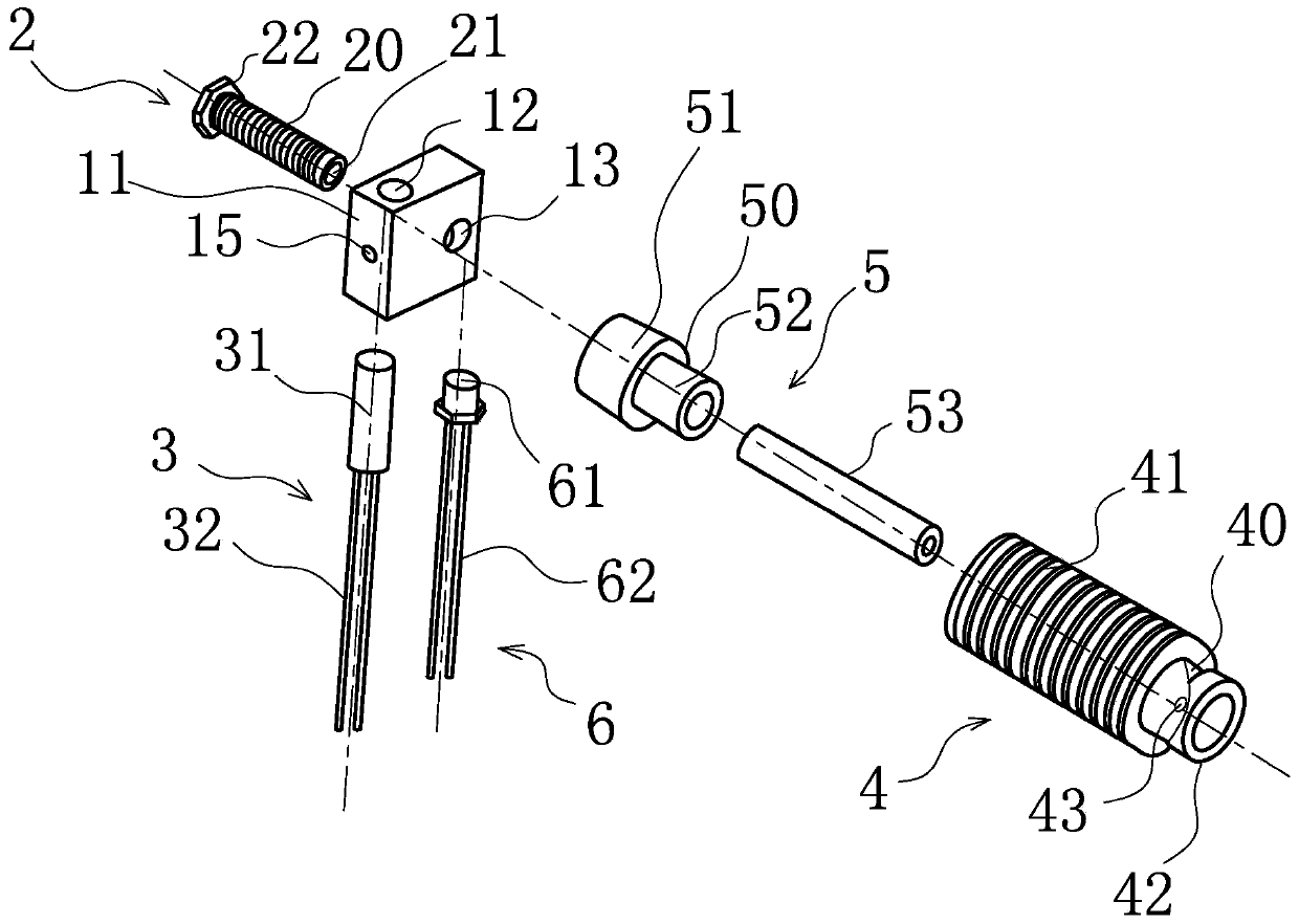
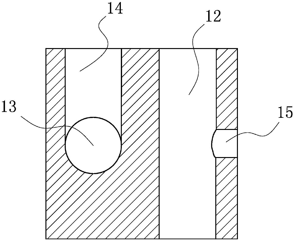
[0023] Such as figure 1 , figure 2 , image 3 As shown, a print head nozzle structure of a 3D printer includes a heating mechanism 1, the heating mechanism 1 is provided with a nozzle assembly 2 and a heating assembly 3, the heating mechanism 1 is connected to a cylindrical heat dissipation mechanism 4, the heating mechanism 1 and A heat insulation mechanism 5 is also provided between the heat dissipation mechanisms 4, and the heat insulation mechanism 5 communicates with the nozzle assembly 2 and the heat dissipation mechanism 4. The heat insulation mechanism 5 is made of low thermal conductivity plastic. The heat insulation mechanism 5 can effectively block the heat from the heating mechanism 1 from being conducted to the heat dissipation mechanism 4. On the one hand, it can prevent the heat from the heating mechanism 1 from bein...


PUM


Abstract

The invention belongs to the technical field of printing equipment, relates to a printing head sprayer structure of a 3D (3-dimensional) printer, and solves the technical problems of high energy consumption, low silk discharging efficiency of a sprayer, high possibility of blocking the sprayer, difficulty for consumable material extrusion and the like in the prior art. The printing head sprayer structure comprises a heating mechanism in which a nozzle assembly and a heating assembly are arranged, wherein the heating mechanism is connected with a barrel-shaped heat dissipating mechanism; a heat insulation mechanism is arranged between the heating mechanism and the heat dissipating mechanism and is communicated with the nozzle assembly and the heat dissipating mechanism. The printing head sprayer structure has the advantages of low energy consumption, high silk discharging efficiency, low possibility of blocking a nozzle, simplicity for consumable material extrusion and the like.

Description

technical field [0001] The invention belongs to the technical field of printing equipment, and relates to a nozzle structure of a printer, in particular to a nozzle structure of a print head of a 3D printer. Background technique [0002] 3D printer is a digital model file-based technology that uses bondable materials such as powdered metal or plastic to construct objects by layer-by-layer printing. In the past, it was often used to make models in the fields of mold manufacturing and industrial design, and is now gradually being used in the direct manufacture of some products. [0003] In 3D printing, software completes a series of digital slices through computer-aided design (CAD) and sends information about those slices to a 3D printer, which stacks successive thin layers until a solid object is formed. There are various forms of stacking thin layers. Some 3D printers use an "inkjet" method. For example, an Israeli 3D printer company called Objet uses a printer nozzle to...

Claims


Application Information

Patent Timeline
IPC IPC(8): B29C67/00
Inventor 冯传孙汉明黄朝晖吴凯赵海斌
Owner 德清中科金融信息技术研究所
Why Eureka
Try Eureka