Method for blocking hydrogen-sulfide-contained water bursting point on bottom plate in grouting mode

A water inrush point and hydrogen sulfide technology, which is applied in earthwork drilling, wellbore lining, tunnel lining, etc., can solve the problems of unreachable grouting pressure, hydrogen sulfide escape, and failure to block, so as to reduce the risk of water inrush again Possibility, improvement of grouting efficiency, and cost-saving effects

Active Publication Date: 2014-04-23
SHAANXI COAL & CHEM TECH INST
View PDF6 Cites 12 Cited by
  • Summary
  • Abstract
  • Description
  • Claims
  • Application Information

AI Technical Summary

Problems solved by technology

[0003] 1) The cement-based slurry is not easy to coagulate quickly in the environment of water inrush, and the effective diffusion radius is small, so it cannot complete the effective plugging of the water inrush aquifer
[0004] 2) When grouting, the water inrush point is a broken zone, and it is difficult to guarantee the effect of grouting for one-time grouting, and it is easy to cause grouting, and the grouting pressure cannot be reached
[0005] 3) When the grout contains a certain amount of cement, the aqueous solution of hydrogen sulfide gas is acidic and corrosive to cement. The durability after grouting is poor, and it is easy to cause hydrogen sulfide to escape, and a very small amount of hydrogen sulfide can also harm the human body. healthy
[0006] 4) Cement cannot seal small pores and cracks, so the overall sealing performance is poor after cement sealing, which is easy to cause hydrogen sulfide to escape

Method used


Image

  • Method for blocking hydrogen-sulfide-contained water bursting point on bottom plate in grouting mode
  • Method for blocking hydrogen-sulfide-contained water bursting point on bottom plate in grouting mode

Examples


Embodiment Construction

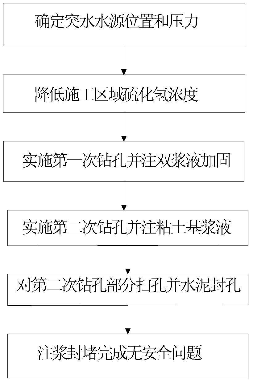
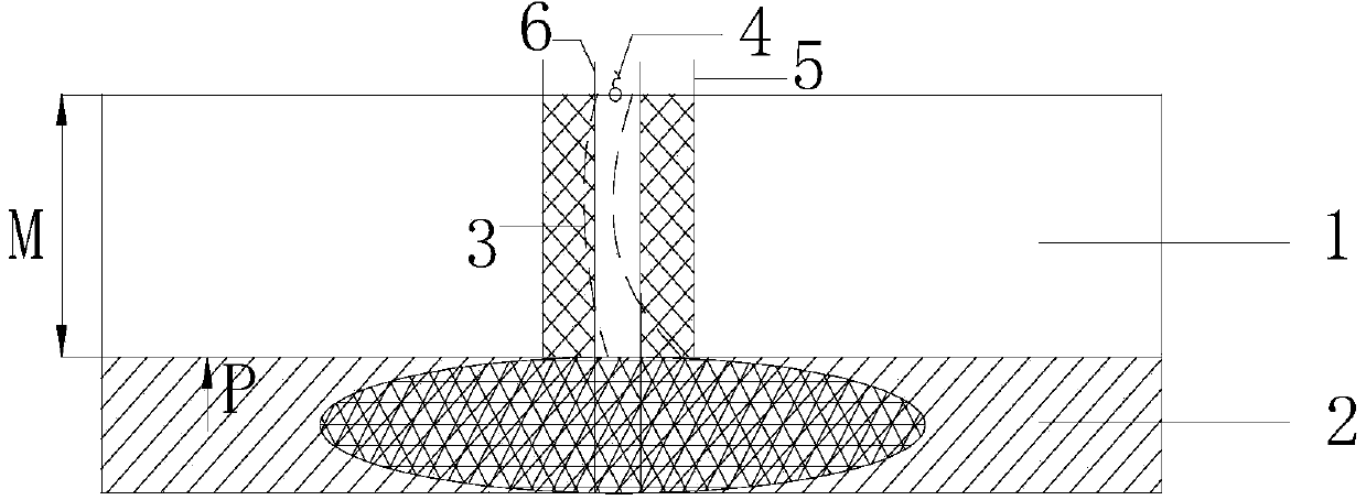
[0023] like figure 1 , figure 2 Shown, a kind of method for floor grouting plugging hydrogen sulfide water inrush point, comprises the following steps:

[0024] Step 1: According to the water quality test results at the water inrush point 4, it is determined that the water inrush at the water inrush point 4 comes from the floor aquifer 2. And through the coalfield geological exploration results, the thickness M of the floor aquifer 1 between the water inrush point 4 and the floor aquifer 2 is obtained from the drilling histogram, and the hydrostatic pressure exerted by the floor aquifer 2 on the floor aquifer 1 p.

[0025] Step 2: Strengthen ventilation and spray lye on the ground near the water inrush point 4, so that the vicinity of the water inrush point can reach the established construction operation environment, that is, the concentration of hydrogen sulfide gas is reduced to a safe range below 0.00066%.

[0026] Step 3: At the water inrush point 4, implement the fir...


PUM


Abstract

The invention provides a method for blocking a hydrogen-sulfide-contained water bursting point on a bottom plate in a grouting mode. The method includes the steps of firstly, carrying out primary hole drilling on the water bursting point, wherein the drilling direction is perpendicularly downward, and the drilling depth is smaller than the thickness M of a water-resisting layer of the bottom plate; secondly, grouting two types of size including cement and water glass into a primarily-drilled hole to conduct rapid grouting blocking, and carrying out secondary hole drilling to the position below the bottom of the water-bearing layer of the bottom plate after the size in the primarily-drilled hole solidifies, wherein the aperture of a secondarily-drilled hole is smaller than that of the primarily-drilled hole, and the drilling direction of the secondary drilling is perpendicularly downward; thirdly, grouting the size formed by clay, quick lime and desulphurization ash into the water-bearing layer, carrying out hole bottom cleaning on the portion, located in the water-resisting layer of the bottom plate, of the secondarily-drilled hole after the secondary grouting is completed, and then conducting cement hole sealing and reinforcing on the cleaned portion of the secondarily-drilled hole; fourthly, blocking a water bursting passageway of the water bursting point.

Description

Technical field: [0001] The invention relates to the field of mine hydrogeology, in particular to a method for plugging hydrogen sulfide water inrush points by floor grouting. Background technique: [0002] There are natural or excavation-induced water-conducting cracks in the bottom plate exposed by the roadway. After the roadway is formed, the water on the bottom plate will gushes out continuously. Some water bodies are near the coal-measure strata, and the sulfur element in the coal-measure strata will slowly hydrolyze in the water to produce hydrogen sulfide. Gas, while hydrogen sulfide is easily soluble in water. With the flooding of the floor, the concentration of hydrogen sulfide in the roadway will increase, which seriously threatens the safety of operators and is corrosive to mining metal instruments. At present, a mixture of cement and other materials is often used to directly block the water inrush point at one time. However, when the water is rich in hydrogen sul...

Claims


Application Information

Patent Timeline
Patent Type & Authority Applications(China)
IPC IPC(8): E21D11/38
Inventor 李涛王苏健邓增社陈通冯海高颖
Owner SHAANXI COAL & CHEM TECH INST
Why Eureka
Try Eureka