Low-voltage load test method and device

A technology with load test and low voltage, applied in the field of power system, to achieve the effect of strong applicability, flexible and convenient testing, and ensuring system safety

Active Publication Date: 2014-04-23
GUANGZHOU POWER SUPPLY BUREAU GUANGDONG POWER GRID CO LTD
View PDF6 Cites 7 Cited by
  • Summary
  • Abstract
  • Description
  • Claims
  • Application Information

AI Technical Summary

Problems solved by technology

[0005] In addition, the traditional load test method itself has certain risks. It is not known whether the polarity is correct before the load is applied, and various complicated safety measures need to be taken (such as: exiting the busbar protection due to uncertain polarity, automatic switching of the backup power supply, safety and stability system, line or main transformer differential protection, protection related to power direction, etc.), these safety measures themselves bring great risks to the system

Method used


Image

  • Low-voltage load test method and device
  • Low-voltage load test method and device
  • Low-voltage load test method and device

Examples


Embodiment Construction

[0028] In order to make the objectives, technical solutions and advantages of the present invention clearer, the following further describes the present invention in detail with reference to the accompanying drawings and embodiments. It should be understood that the specific embodiments described herein are only used to explain the present invention, but not to limit the present invention.

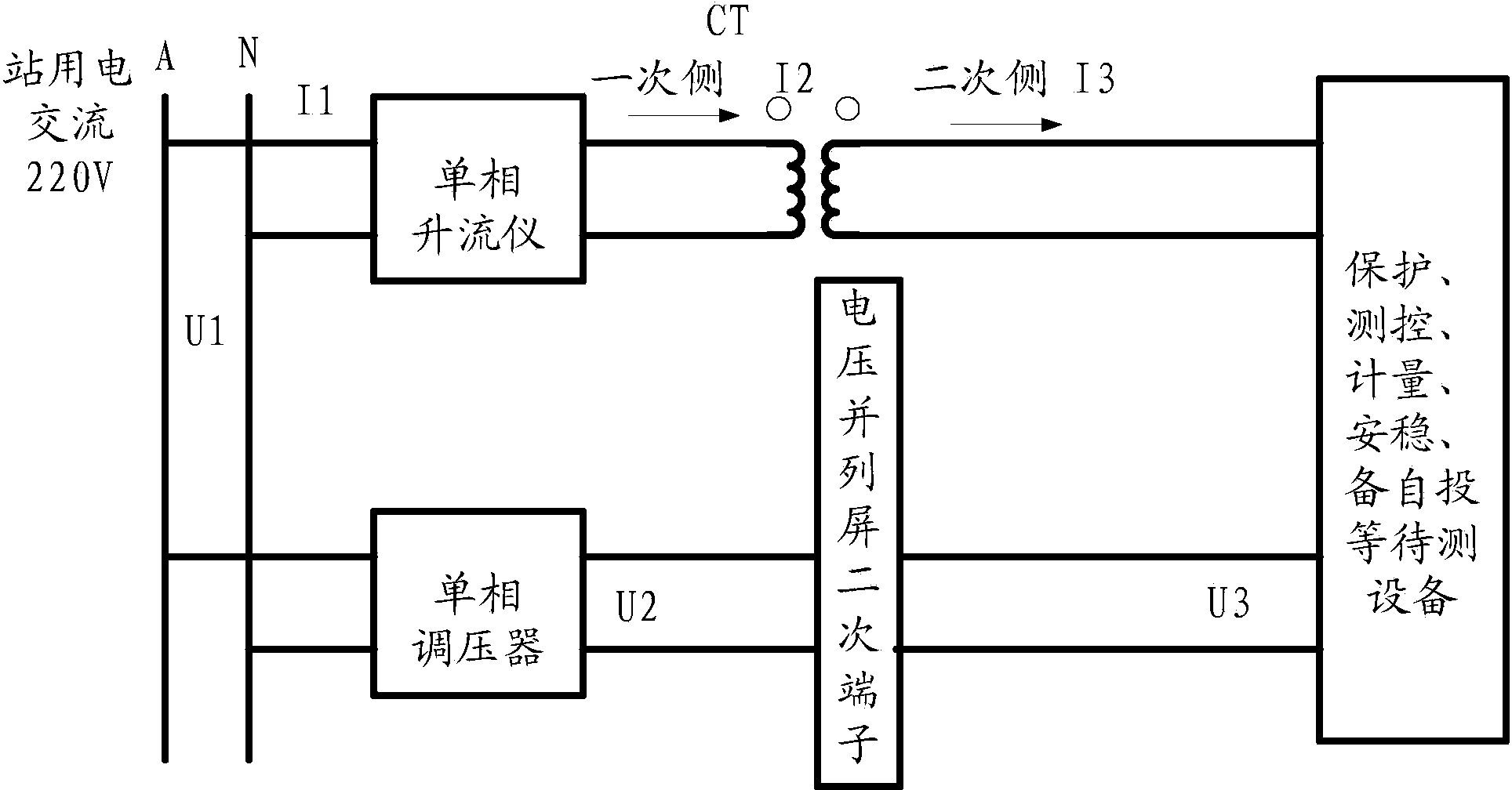
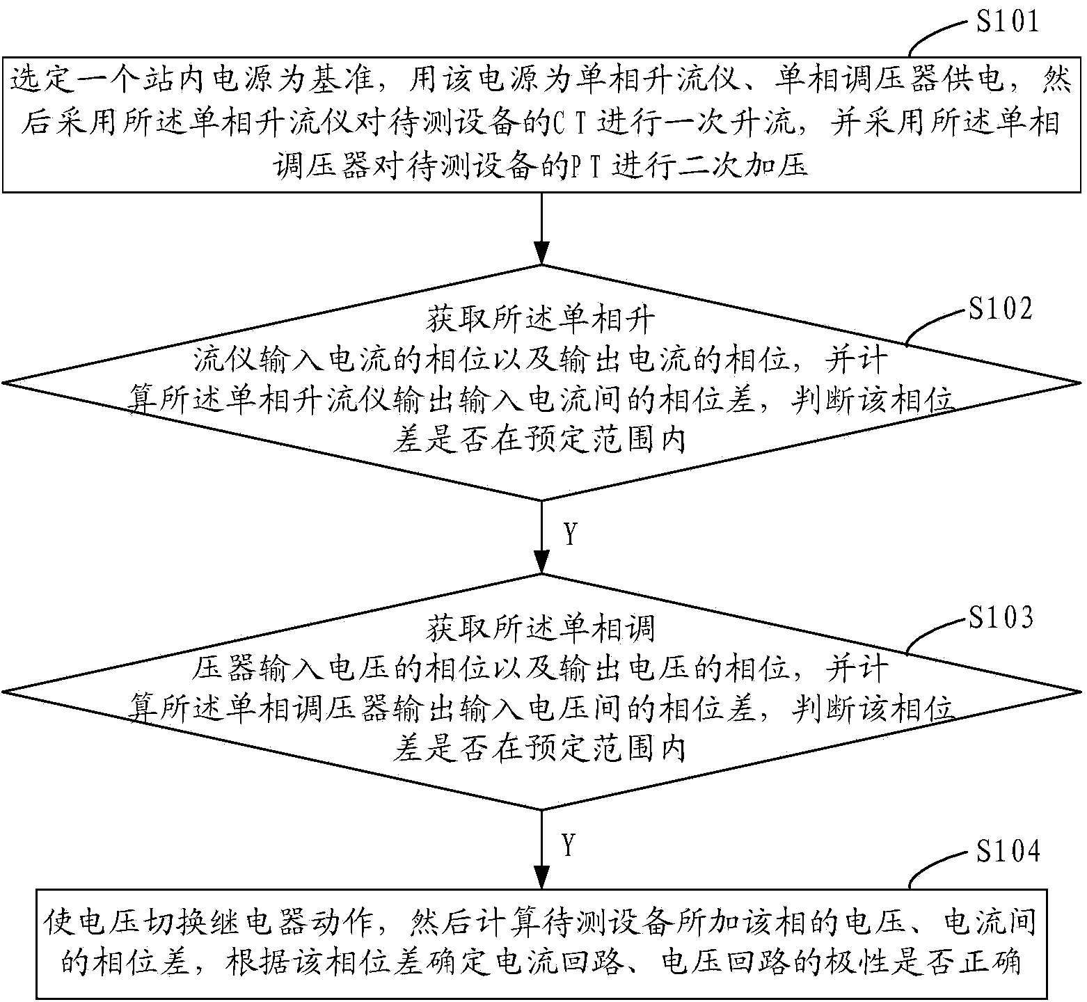
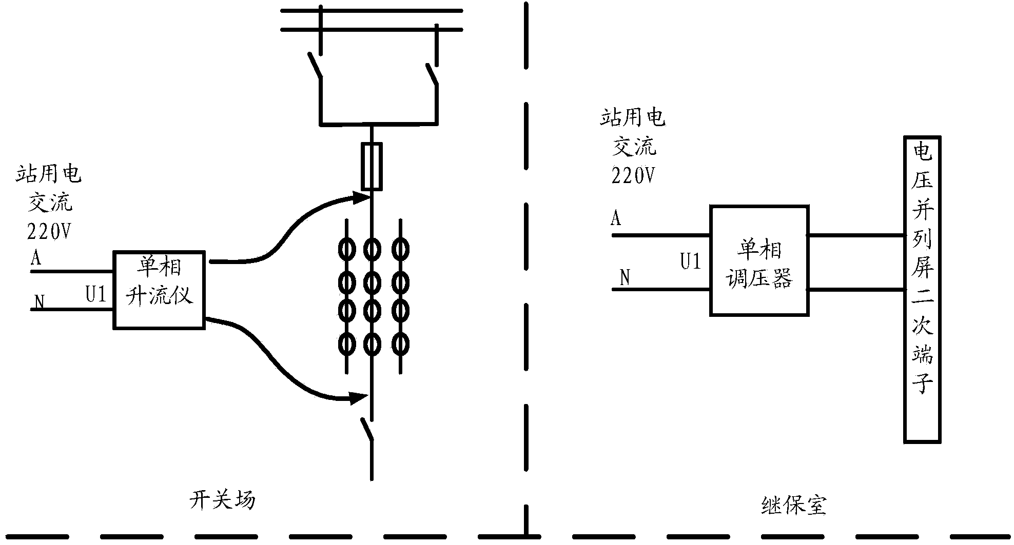
[0029] In the present invention, a low-voltage load test method that replaces the high-voltage load test method of traditional power transmission equipment is provided. It can find a benchmark to compare with the measured secondary value without the primary high-voltage load test method. The benchmark is Station power supply or construction power supply in the substation. Assuming that the 220V power supply in the same station is used as a reference, power is supplied to a single-phase upflow meter and a single-phase voltage regulator. Use a single-phase up-current meter to add CT primary si...


PUM


Abstract

The invention provides a low-voltage load test method and device. The method comprises the following steps of selecting an instation power supply as a benchmark, powering a single-phase riser instrument and a single-phase voltage regulator by utilizing the power supply, primarily increasing the current of a CT of a device to be tested by utilizing the single-phase riser instrument, and secondarily boosting the voltage of a PT of the device to be tested by utilizing the single-phase voltage regulator; acquiring the phase of the input current and the output current of the single-phase riser instrument, calculating the phase difference, and judging whether the phase difference stays within the predetermined range; acquiring the phase of the input voltage and the phase of the output voltage of the single-phase voltage regulator if the phase difference stays in the predetermined range, calculating the phase difference, and judging the phase differences stays in a predetermined range; switching the voltage to a relay if the phase difference of the input voltage and the output voltage stays in the predetermined range, calculating the phase difference between the voltage and the current of the phase of the device to be tested, and determining whether the polarity of a current loop and a voltage loop is correct or not according to the phase difference. The test method is flexible, convenient, strong in practicability, high in working efficiency and capable of guaranteeing the safety of the system.

Description

Technical field [0001] The invention relates to the field of electric power systems, in particular to a low-voltage load test method and a low-voltage load test device. Background technique [0002] Newly built or rebuilt power transmission equipment (such as power transmission lines, transformers, etc.), before transmitting power to users, meet the requirements of relay protection, measurement monitoring, metering and billing, and power transmission. It is necessary to carry out a load test to determine whether the polarity of the current loop and voltage loop of the power transmission equipment is correct. [0003] The traditional load test method is to carry the primary equipment with a large system and directly charge the equipment with actual current to carry out the load test. In order to check the correctness of the secondary current circuit and voltage circuit, namely the secondary circuit of CT (current transformer) and PT (Potential transformer, voltage transformer), the...

Claims


Application Information

Patent Timeline
Patent Type & Authority Applications(China)
IPC IPC(8): G01R31/06G01R29/20
Inventor 徐强超顾晓凌江文东麦胜贤
Owner GUANGZHOU POWER SUPPLY BUREAU GUANGDONG POWER GRID CO LTD
Why Eureka
Try Eureka