Vehicle-mounted charger circuit

An on-board charger and circuit technology, used in hybrid) vehicles and electric (pure electric fields), can solve problems such as inability to achieve independent control, and achieve the effects of reducing cost and volume, improving utilization, and independent voltage control.

Active Publication Date: 2014-04-23
UNITED AUTOMOTIVE ELECTRONICS SYST
View PDF2 Cites 35 Cited by
  • Summary
  • Abstract
  • Description
  • Claims
  • Application Information

AI Technical Summary

Problems solved by technology

In the multi-output full-bridge topology, since the transformer windings reuse the same magnetic core, there is a coupling relationship between the output voltages, which present an integer multiple of the turn ratio, and independent control cannot be achieved.
Due to the relatively large variation range of the high and low voltage battery voltage, the output voltage of the charger is required to vary within a certain range. If the multiple windings on the secondary side of the full bridge are simply coupled to the same magnetic core coil, the requirements cannot be met.

Method used


Image

  • Vehicle-mounted charger circuit
  • Vehicle-mounted charger circuit
  • Vehicle-mounted charger circuit

Examples


Embodiment 1

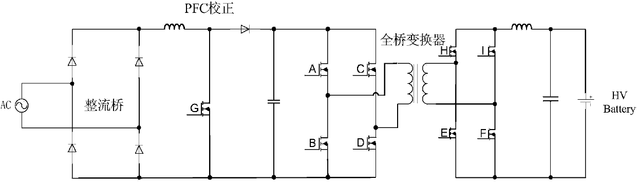
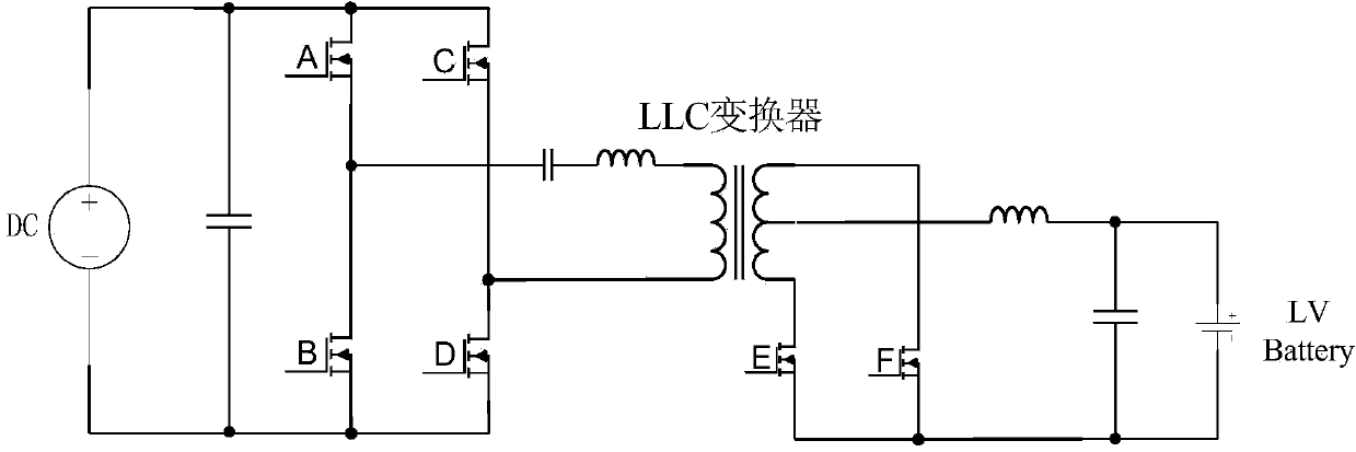
[0045] On-board charger circuits such as Figure 4 , Figure 5 As shown, including multiple output full bridge conversion circuit, PWM (Pulse Width Modulation) controller;

[0046] The multi-output full-bridge conversion circuit includes a first capacitor C1, a first switch M1, a second switch M2, a third switch M3, a fourth switch M4, a first inductor L1, a second capacitor C2, A transformer, a first rectifier circuit, a third capacitor C3, a second rectifier circuit, a fourth capacitor C4, and a second inductor L2;

[0047] The two ends of the first capacitor C1 are used as two input ends of a multi-output full-bridge conversion circuit for connecting to a DC voltage;

[0048] The first switching tube M1 and the second switching tube M2 are connected in series between two input terminals of the multi-output full-bridge conversion circuit;

[0049] The third switching tube M3 and the fourth switching tube M4 are connected in series between the two input terminals of the mu...

Embodiment 2

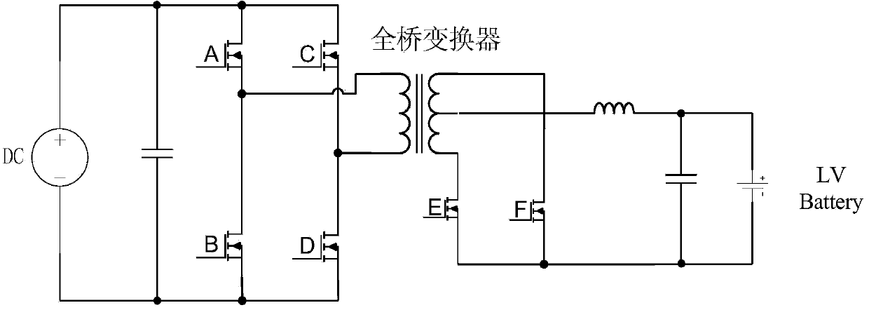
[0072] Such as Figure 6 The car charger circuit shown is the same as that of Embodiment 1 Figure 5 The difference between the shown circuits is that the multi-output full-bridge conversion circuit also includes a fifth capacitor C5;

[0073] The fifth capacitor C5 is connected between the two ends of the primary winding of the transformer, and the frequency of the PWM control signal is greater than

[0074] L1 is the first inductor, C2 is the second capacitor, and C5 is the fifth capacitor.


PUM


Abstract

The invention discloses a vehicle-mounted charger circuit, which has two working modes, i.e. a high-voltage charging mode and a low-voltage charging mode. When the vehicle-mounted charger circuit works in the high-voltage charging mode, the vehicle-mounted charger circuit respectively charges high-voltage and low-voltage batteries, a PWM (Pulse Width Modulation) controller outputs PWM control signals with frequency which is higher than resonant frequency to control a switching tube, direct-current high-voltage power is output through a first winding on the secondary side of a transformer, a first rectifier circuit and a third capacitor to charge high-voltage batteries and direct-current low-voltage power is output through a second winding on the secondary side of the transformer, a second rectifier circuit, a second inductor and a fourth capacitor to charge low-voltage batteries; when the vehicle-mounted charger circuit works in the low-voltage charging mode, the PWM controller controls the switching tube to be turned off and high-voltage battery energy is output to charge low-voltage batteries through the transformer. The vehicle-mounted charger circuit disclosed by the invention can realize independent voltage control during full-bridge dual-winding output.

Description

technical field [0001] The invention relates to electric (pure electric, hybrid) vehicle technology, in particular to a vehicle charger circuit. Background technique [0002] As new energy vehicles gradually enter the market, the market's demand for on-board chargers is increasing. In electric (pure electric, hybrid) vehicles, high-voltage battery chargers (Charger) and low-voltage battery chargers (Converter) are the key The electrical equipment is responsible for charging the high-voltage battery and the low-voltage battery respectively. The two usually exist independently in the vehicle and complete their respective functions. Currently, it is increasingly difficult for independent chargers to meet the high integration and low cost requirements of OEMs. With the increasingly urgent demand for high power density and highly integrated chargers from OEMs, a new type of charger (Charcon) integrating the concept of a high-voltage battery charger (Charger) and a low-voltage ba...

Claims


Application Information

Patent Timeline
Patent Type & Authority Applications(China)
IPC IPC(8): H02J7/00H02M7/217
Inventor 付登萌刘少伟王小昆王兴
Owner UNITED AUTOMOTIVE ELECTRONICS SYST
Why Eureka
Try Eureka