High step-up ratio converter for DC (Direct Current) module on basis of coupled inductors

A technology of coupled inductance and high boost ratio, applied in the direction of conversion equipment without intermediate conversion to AC, can solve the problems of complex coupled inductance structure, reduce conduction loss, large switching loss, etc., achieve simple circuit structure, reduce voltage Stress, the effect of reducing conduction loss

Inactive Publication Date: 2014-04-23
HOYMILES POWER ELECTRONICS INC
View PDF6 Cites 3 Cited by
  • Summary
  • Abstract
  • Description
  • Claims
  • Application Information

AI Technical Summary

Problems solved by technology

[0003] The voltage gain of the conventional interleaved parallel boost DC-DC converter is only determined by the duty cycle, the voltage gain is limited, and it is difficult to meet the conversion requirements of high gain
The voltage stress of the power switch tube is relatively large, and it is difficult to use a low-voltage high-performance switch tube to reduce the conduction loss
Moreover, the converter works in a hard switching state, and the switching loss is relatively large
In order to realize the soft switching action of the Boost converter, in recent years, some soft switching schemes by adding active power switches or passive devices have been studied successively. Although these circuits realize the soft switching action, they cannot reduce the voltage stress of the switching tube. It is also impossible to realize the high-gain conversion of the system
In order to increase the voltage gain of the converter, one solution is to use switched capacitors, but this solution requires a large number of switch tubes, which increases the system cost; another solution is to use a complex three-winding coupled inductor solution. The disadvantage of the scheme is that the structure of the coupled inductor is complex, which is not conducive to industrial processing, and it is difficult to ensure the consistency of the circuit

Method used


Image

  • High step-up ratio converter for DC (Direct Current) module on basis of coupled inductors

Examples


Embodiment Construction

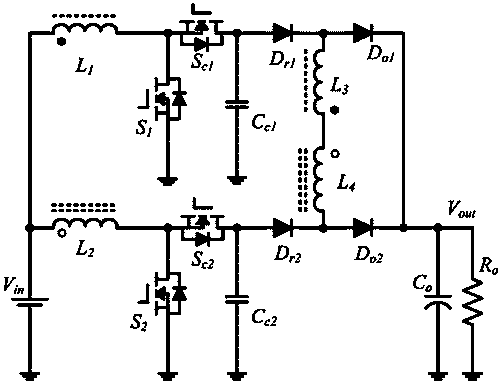
[0015] see figure 1 , the high step-up ratio converter for DC modules based on coupled inductors of the present invention includes a Boost step-up circuit unit, a freewheeling step-up circuit unit and an output circuit unit.

[0016] In the boost circuit unit of the converter, the first end of the first winding L1 is connected to the first end of the second winding L2 and the positive pole of the power supply Vin, and the second end of the first winding L1 is connected to the drain of the first switching tube S1 The poles are connected, the second end of the second winding L2 is connected to the drain of the second switching tube S2, the source of the first switching tube S1 is connected to the source of the second switching tube S2 and the negative pole of the power supply Vin, and the first clamp The source of the switching tube Sc1 is connected to the drain of the first switching tube S1, the drain of the first clamping switching tube Sc1 is connected to the first end of th...


PUM


Abstract

The invention discloses a high step-up ratio converter for a DC (Direct Current) module on the basis of coupled inductors, which comprises two main switching tubes, two clamping switching tubes, two freewheel diodes, two output diodes, two clamping capacitors, two voltage-multiplying capacitors, an output capacitor and tow coupled inductors each of which is respectively provided with two windings. According to the invention, a voltage gain of the converter is expanded and voltage stresses of the power switching tubes and the diodes are reduced by the coupled inductors; the leakage inductances of the coupled inductors are utilized to implement zero voltage switching of the switching tubes and inhibit reverse recovery currents of the diodes; a clamping circuit consisting of the clamping switching tubes and the clamping capacitors effectively adsorbs a voltage spike when the power switching tubes are switched on and switched off and implements lossless transfer of energy; a coupled inductor series circuit is utilized to further improve the gain of the converter and further reduce the voltage stresses of the power switching tubes and the output diodes; the high step-up ratio converter has a simple circuit structure, is convenient to control and is suitable for the high-gain and high-efficiency grid-connected photovoltaic power generation transformation place.

Description

technical field [0001] The invention relates to a DC-DC converter and its application, in particular to a converter with a high step-up ratio for a DC module based on coupled inductance. Background technique [0002] In the solar power generation system, since the output voltage of a single solar cell is low, and the voltage required for inverter grid-connected power generation is relatively high, a first-stage DC-DC converter is required to convert low-voltage DC power into a high voltage suitable for grid-connected power generation. Voltage DC. In the distributed solar power generation scheme, the power capacity of a single solar cell is small, but the requirement for efficiency is high. Therefore, how to realize a single-phase single-stage converter with high gain, high efficiency and simple structure is of great significance for promoting the development of the photovoltaic industry. [0003] The voltage gain of the conventional interleaved parallel boost DC-DC convert...

Claims


Application Information

Patent Timeline
Patent Type & Authority Applications(China)
IPC IPC(8): H02M3/10
Inventor 赵一杨波
Owner HOYMILES POWER ELECTRONICS INC
Why Eureka
Try Eureka