Power supply circuit, control circuit for heating device and heating device

A technology of power supply circuit and control circuit, applied in induction heating control, induction heating, output power conversion device and other directions, can solve the problems of life reduction of working devices, fluctuation and damage of rectified output voltage, and achieve stable voltage and stable working voltage. Effect

Inactive Publication Date: 2014-04-23
MIDEA GRP CO LTD +1
View PDF4 Cites 2 Cited by
  • Summary
  • Abstract
  • Description
  • Claims
  • Application Information

AI Technical Summary

Problems solved by technology

The biggest feature of these three circuits is that the voltage of the main power circuit is determined by the input AC power supply voltage. Once the AC input voltage is fixed, the output voltage of the rectifier circuit cannot be adjusted. The induction cooker can only adjust the frequency and duty cycle of the heating transistor. Get different power (firepower); and when the AC voltage fluctuates, the rectified output voltage also fluctuates, which leads to the instability of the subsequent heating control circuit. When the AC input is too high, the transistor heated by a single tube may be overvoltage Impact may cause damage; while half-bridge and full-bridge induction cookers heat aluminum and copper pans due to high resonant frequency, the current peak value of the transistor is also high, voltage fluctuations are likely to cause the transistor current to exceed the range and overheat damage ; If the input voltage is very high, the high-frequency pulse current flowing through the transistor when the copper and aluminum pans are inspected is also very large, and the life of the device will decrease if it works for a long time
Since the output voltage cannot be adjusted after the AC voltage is rectified, it is also difficult for the induction cooker to achieve continuous low-power or high-power heating

Method used


Image

  • Power supply circuit, control circuit for heating device and heating device
  • Power supply circuit, control circuit for heating device and heating device
  • Power supply circuit, control circuit for heating device and heating device

Examples


Embodiment approach 1

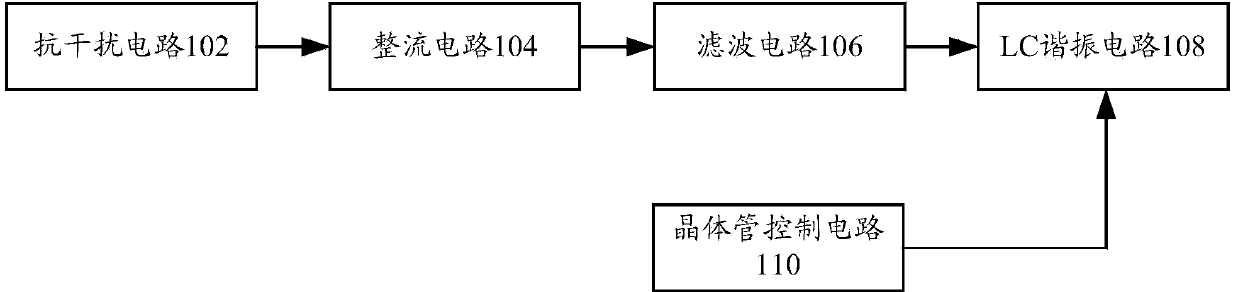
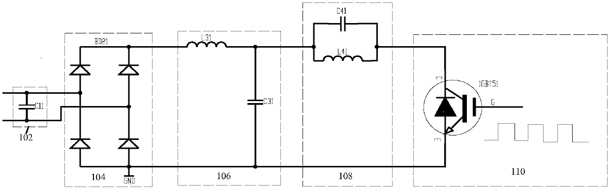
[0065] like Figure 9 and Figure 10 As shown, when the power supply circuit 700 is applied to the circuit of the electromagnetic heating device, and the control circuit of the electromagnetic heating device adopts a transistor (that is, a single-tube solution), the connection mode of the circuit is: the output of the anti-interference circuit 702 is connected to the rectifier circuit The input terminal of 704, the output terminal of the rectifier circuit 704 is connected to the input terminal of the filter circuit 706, the first filter circuit 706 includes capacitors C31, C32 and inductor L31, the capacitors C31, C32 and inductor L31 form a Π-type filter, and simultaneously connected in series Resistors R31, R32 and R33 can also be used as a discharge circuit for the post-rectification stage at no-load. One end of the resistors is connected to the output end of the rectifier bridge, and the other end is grounded for discharge. The buck-boost circuit 708 is composed of an ind...

Embodiment approach 2

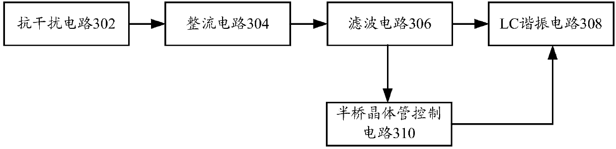
[0069] like Figure 11 and Figure 12 As shown, when the power supply circuit 700 is applied to the circuit of the electromagnetic heating device, and the control circuit of the electromagnetic heating device adopts two transistors (i.e. the half-bridge scheme), the connection mode of the circuit is: the buck-boost circuit 708 and the implementation mode One is the same, the output of the buck-boost circuit 708 is filtered by C51 and C52 of the second filter circuit 1108, and then connected to one end of C71 and C72 of the resonant circuit 1102, and connected to the C pole of IGBT61 and the E pole of IGBT62 of the control circuit 1104 . The control circuit 1104 includes IGBT61, IGBT62, C61 and C62, and C61 and C62 are used as the absorbing capacitance of the C pole of the IGBT to reduce the impact of high-frequency current on the IGBT61 and IGBT62. The resonant circuit 1102 includes resonant inductors L71, C71 and C72, C71 and C72 is a resonant capacitor, wherein the resonan...

Embodiment approach 3

[0071] like Figure 14 and Figure 15 As shown, when the power supply circuit 700 is applied to the circuit of the electromagnetic heating device, and the control circuit of the electromagnetic heating device adopts four transistors (that is, the full-bridge scheme), the connection mode of the circuit is: the front-stage part circuit of the full-bridge scheme (i.e. the power supply circuit 700) is the same as the circuit in the second embodiment, the output of the second filter circuit 1408 is connected to both ends of multiple control circuits 1404 (i.e. the control circuit 14042 and the control circuit 14044), that is, respectively connected to the C poles of the IGBT61 , the E pole of IGBT62, the C pole of IGBT71 and the E pole of IGBT72, the control circuit 14042 includes IGBT61, IGBT62, C61, C62, R61 and R62, C61, C62, R61 and R62 as IGBT interference absorption circuit components, IGBT control circuit 14044 Including IGBT71, IGBT72, C71, C72, R71 and R72, C71, C72, R71 ...


PUM


Abstract

The invention provides a power supply circuit, which comprises a rectification circuit, a first filtering circuit, a boost-buck circuit and a controller, wherein the input end of the rectification circuit is connected to an alternating current power source to receive alternating current output by the alternating current power source and carry out rectification processing on the alternating current to obtain first direct current; the input end of the first filtering circuit is connected to the output end of the rectification circuit to carry out filtering processing on the first direct current so as to obtain second direct current; the input end of the boost-buck circuit is connected to the output end of the first filtering circuit to regulate the second direct current according to a received control signal so as to obtain third direct current, the first output end of the boost-buck circuit outputs the second direct current, and the second output end outputs third direct current; and the controller is connected to the boost-buck circuit to send a control signal to the boost-buck circuit. Correspondingly, the invention also provides a control circuit for a heating device and a heating device. According to the technical scheme, the output voltage of the power supply circuit can be regulated at will to satisfy different voltage requirements of users and provide the stable voltage for the users.

Description

technical field [0001] The invention relates to the technical field of heating, in particular to a power supply circuit, a control circuit of a heating device and a heating device. Background technique [0002] The existing induction cooker heating schemes mainly include single-tube, half-bridge and full-bridge circuit schemes, among which the block diagram and circuit structure of the main circuit of the induction cooker for the single-tube scheme are as follows: figure 1 and figure 2 As shown, it generally includes an anti-interference circuit 102 , a rectifier circuit 104 , a filter circuit 106 , an LC resonant circuit 108 , and a transistor control circuit 110 . The block diagram and circuit structure of the main circuit of the induction cooker in the half-bridge scheme are as follows: image 3 and Figure 4 As shown, it generally includes an anti-interference circuit 302 , a rectifier circuit 304 , a filter circuit 306 , an LC resonant circuit 308 , and a half-bridg...

Claims


Application Information

Patent Timeline
Patent Type & Authority Applications(China)
IPC IPC(8): H02M7/217H05B6/06
Inventor 李昌梁为磊冯江平
Owner MIDEA GRP CO LTD
Why Eureka
Try Eureka