Eureka AIR delivers breakthrough ideas for toughest innovation challenges, trusted by R&D personnel around the world.

Quick recovery method of remote sensing image based on vibration detection of fiber-optic gyroscope and coding exposure

A technology of coding exposure and fiber optic gyro, which is used in image communication, image enhancement, image data processing, etc., can solve the problems of slow operation speed, application limitation, and high algorithm complexity, and achieve the effect of fast recovery speed and good effect.

Inactive Publication Date: 2014-04-23
ZHEJIANG UNIV
View PDF2 Cites 6 Cited by
  • Summary
  • Abstract
  • Description
  • Claims
  • Application Information

AI Technical Summary

Problems solved by technology

The early inverse filtering method is to transform the convolution relationship in the spatial domain into the dot product relationship in the frequency domain according to the nature of the Fourier transform. To obtain the restored image, it is only necessary to compare the Fourier transform result of the blurred image with the Fourier transform result of the PSF. It is enough to divide and do inverse Fourier transform, but the premise of this method is that the filter that causes image degradation is reversible, and usually, the inverse filtering method is caused by the irreversible filter in the image degradation model or the inverse filter is not stable enough. It is very sensitive to noise in the image. In the case of large noise, the effect of image restoration is not ideal, so its application is greatly limited.
As for PSF reconstruction algorithms, many have an obvious disadvantage, that is, the algorithm complexity is high, the operation speed is slow, or the operation speed can be improved under the premise of sacrificing the clarity of the restored image.

Method used


Image

  • Quick recovery method of remote sensing image based on vibration detection of fiber-optic gyroscope and coding exposure
  • Quick recovery method of remote sensing image based on vibration detection of fiber-optic gyroscope and coding exposure
  • Quick recovery method of remote sensing image based on vibration detection of fiber-optic gyroscope and coding exposure

Examples


Embodiment Construction

[0038] The present invention will be further described below in conjunction with accompanying drawing.

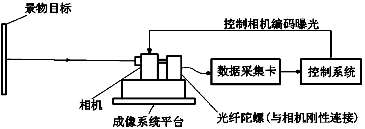
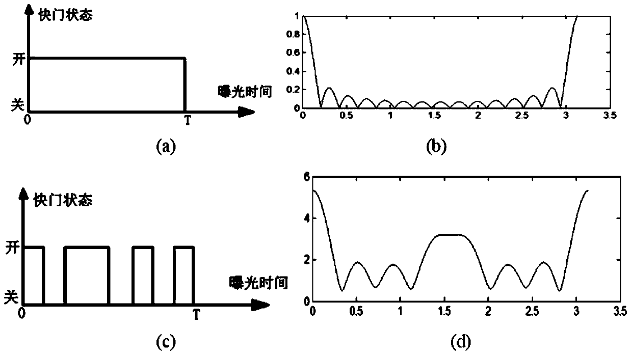
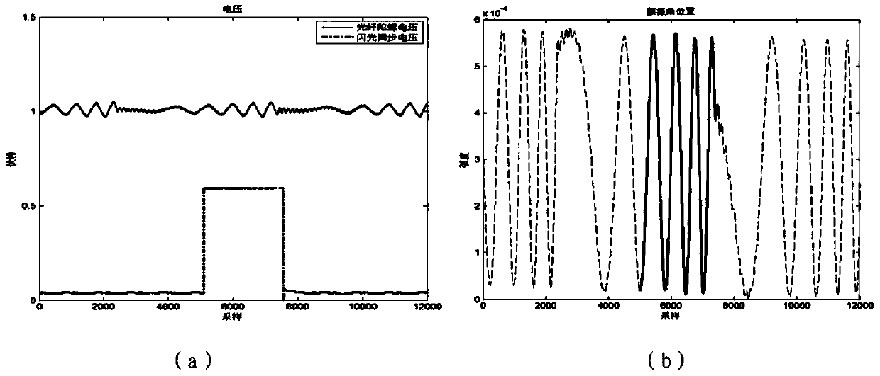
[0039] The present invention is a remote sensing image rapid recovery method based on fiber optic gyroscope vibration detection and coding exposure, which uses a dual-axis fiber optic gyroscope to detect the vibration process of the imaging system platform in real time, and at the same time the imaging camera is coded and exposed to obtain remote sensing images, and the control system reads the fiber optic gyroscope The output signal is calculated to obtain the image degradation point spread function, and the remote sensing image obtained by encoding exposure is deconvoluted to eliminate the influence of platform vibration, and a clear remote sensing image is quickly obtained. The system composition of the present invention is as attached figure 1 As shown, it mainly includes three parts: an imaging camera, a fiber optic gyro rigidly connected with the imaging camera, and a...


PUM


Abstract

The invention provides a quick recovery method of a remote sensing image based on vibration detection of a gyroscope and coding exposure. A vibration process of a satellite platform can be detected in real time by adopting a double-shaft fiber-optical gyroscope, the remote sensing image can be simultaneously obtained as an imaging camera is in coding exposure, an image degradation point spread function can be calculated and obtained by a processing system according to vibration data obtained through the measurement of the fiber-optic gyroscope and a time coding value of an exposure process of the imaging camera, the platform vibration influence can be then removed by deconvolution of the remote sensing image, and the clear remote sensing image can be quickly obtained. Since the coding exposure is adopted and the fiber-optic gyroscope is adopted for measuring the platform vibration, the quick recovery method is suitable for obtaining the clear remote sensing image by the satellite platform with complicated vibration.

Description

technical field [0001] The invention relates to a method for acquiring and quickly restoring high-resolution remote sensing images, in particular to a method for rapidly restoring remote sensing images based on fiber optic gyroscope vibration detection and coded exposure. Background technique [0002] In remote sensing imaging, image clarity has very important practical significance. However, during the imaging process of the space camera, due to factors such as satellite attitude changes, disturbances of flexible components, and pointing control, the satellite platform flutters. There is relative motion between them, and the captured image will produce smear, resulting in blurred image, reducing the modulation transfer function of the system and the ground resolution of the image, and cannot fully achieve the resolution capability of the imaging system design. In less-than-ideal lighting conditions, camera exposure times are longer, exacerbating the image blur problem. ...

Claims


Application Information

Patent Timeline
Patent Type & Authority Applications(China)
IPC IPC(8): H04N5/235G06T5/00H04N5/262
Inventor 冯华君何丽蓉黄加紫徐之海李奇陈跃庭
Owner ZHEJIANG UNIV
Why Eureka
Eureka Blog
Learn More