Outer peripheral face polishing machine for bearing outer ring

A technology for the outer ring and outer peripheral surface of a bearing, which is applied to the grinding frame, the machine tool designed for grinding the rotating surface of the workpiece, the grinding machine, etc., which can solve the problems of no grinding and achieve the goal of improving the grinding performance and grinding performance Effect

Active Publication Date: 2014-04-30
HAINING QI SHENG BEARING
View PDF6 Cites 12 Cited by
  • Summary
  • Abstract
  • Description
  • Claims
  • Application Information

AI Technical Summary

Problems solved by technology

[0004] In the prior art, the inner peripheral surface of the inner ring of the bearing is polished by special grinding eq

Method used


Image

  • Outer peripheral face polishing machine for bearing outer ring
  • Outer peripheral face polishing machine for bearing outer ring
  • Outer peripheral face polishing machine for bearing outer ring

Examples


Example Embodiment

[0035] Example one

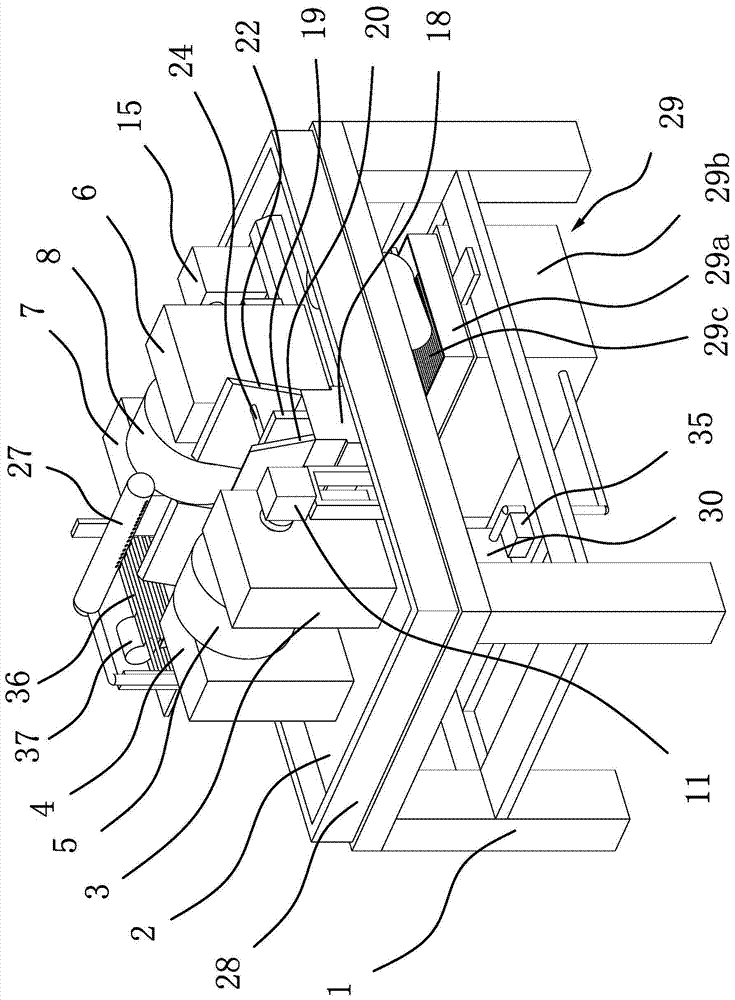
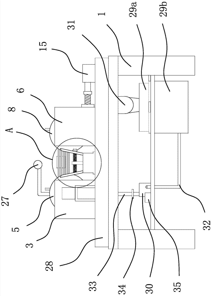
[0036] Such as figure 1 , 2 As shown in and 3, a grinding machine for the outer peripheral surface of the outer ring of a bearing includes a frame 1, on which a table plate 2 is fixed, and four water baffle plates 28 are fixed on the edge of the table plate 2. The water plate 28 encloses a rectangle to enclose the worktable 2 to prevent the water on the worktable 2 from flowing around the worktable 2. There is also a return hole on the worktable 2 to make the worktable The water on the plate 2 can flow out from the return hole.

[0037] Such as figure 1 As shown, the frame 1 includes four legs and a mounting frame fixed at the upper part of the legs. The worktable 2 is installed in the mounting frame. The middle part of the frame 1 is fixed with a horizontal plate 1 and a horizontal plate 2 parallel to each other. Vertical board one and vertical board two parallel to each other. A substrate is also fixed between the horizontal plate 1 and the horizontal plate...

Example Embodiment

[0060] Example two

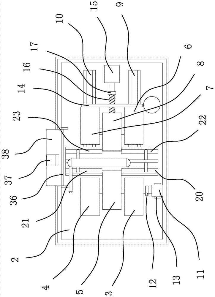
[0061] The structure and principle of this embodiment are basically the same as those of the first embodiment. The difference lies in: in the first embodiment, the power mechanism includes a driving motor 11 and a coupling 12, and the driving motor 11 is fixed in operation by a mounting frame 13 On the platen 2, one end of the coupling 12 is connected with the output shaft of the driving motor 11, and the other end is connected with the rotating shaft 1. In the second embodiment, the power mechanism includes a driving motor 11, a driving pulley, and a driven pulley. And the belt, the driving motor 11 is fixed on the worktable 2 by screws, and the output shaft of the driving motor 11 faces the grinding wheel 5, the driving pulley is fixed on the output shaft of the driving motor 11, and the driven pulley is fixed on the rotating shaft 1. Set between the driving pulley and the driven pulley. Turn on the driving motor 11, and the output shaft of the driving mot...

Example Embodiment

[0062] Example three

[0063] The structure and principle of this embodiment are basically the same as those of the first embodiment. The difference lies in: in the first embodiment, the adjusting mechanism includes an adjusting motor 15, a connecting plate 14, and a screw 16, and the adjusting motor 15 is fixed on the worktable 2. And the output shaft of the adjusting motor 15 faces the positioning wheel 8. One end of the connecting plate 14 is fixed to the bearing seat 326, and the other end is fixed to the bearing seat 427. The middle of the connecting plate 14 is provided with an adjusting hole and a screw 16 One end is threadedly connected to the adjusting hole on the connecting plate 14, and the other end is fixedly connected with the output shaft of the adjusting motor 15 through the coupling two 17. In the third embodiment, the adjusting mechanism includes a cylinder and a connecting block. It is fixed on the worktable 2 and the piston rod of the cylinder faces the positi...


PUM


Abstract

The invention provides an outer peripheral face polishing machine for a bearing outer ring and belongs to the technical field of machinery. The problem in the prior art that a special device for polishing the outer peripheral face of the bearing outer ring is unavailable is solved. The machine comprises a machine frame, a work table board is fixed on the machine frame, a first bearing seat and a second bearing seat which correspond to each other are fixed on the work table board, a grinding wheel is arranged between the first bearing seat and the second bearing seat through a first rotary shaft, and the first rotary shaft is connected with a power mechanism. A third bearing seat and a fourth bearing seat are arranged on the work table board, and a locating wheel is arranged between the third bearing seat and the fourth bearing seat through a second rotary shaft. A first guide track and a second guide track are fixed on the work table board, the third bearing seat and the fourth bearing seat are arranged on the first guide track and the second guide track in a sliding mode respectively, and the third bearing seat and the fourth bearing seat are connected with an adjusting mechanism. The machine can polish the outer peripheral face of the bearing outer ring and is high in efficiency.

Description

technical field [0001] The invention belongs to the technical field of machinery and relates to a grinder, in particular to a grinder for the outer peripheral surface of a bearing outer ring. Background technique [0002] Bearings are components that fix and reduce the friction coefficient of loads during mechanical transmission. It can also be said that when other parts move relative to each other on the shaft, it is used to reduce the friction coefficient in the process of power transmission and keep the center of the shaft fixed. Bearing is an important component in contemporary mechanical equipment. Its main function is to support the mechanical rotating body to reduce the friction coefficient of mechanical load during the transmission process of the equipment. According to the different friction properties of moving elements, bearings can be divided into two types: rolling bearings and sliding bearings. [0003] Bearings are mainly composed of bearing inner rings, bea...

Claims


Application Information

Patent Timeline
IPC IPC(8): B24B5/36B24B5/35B24B55/06
CPCB24B5/35B24B5/355B24B5/36B24B41/005B24B41/02B24B55/00B24B55/06B24B55/12
Inventor 吕咏奇
Owner HAINING QI SHENG BEARING
Why Eureka
Try Eureka