Double cooling system of X-ray machine

A dual-cooling, X-ray machine technology, used in refrigerators, compressors, refrigeration components, etc., can solve the problems of high operating costs, large cooling capacity, and decreased cooling efficiency, and achieve the goal of reducing operating costs and downtime. Effect

Active Publication Date: 2014-04-30
MING WEI MEDICAL TECH SUZHOU
View PDF5 Cites 11 Cited by
  • Summary
  • Abstract
  • Description
  • Claims
  • Application Information

AI Technical Summary

Problems solved by technology

[0004] In summary, we can find that the prior art has the following defects: 1) when only the air-cooled system is used, in order to meet the cooling requirements of the instrument and the room, the cavity in the X-ray machine must be required to have a ventilation rate of the room. It is large enough; in addition, in the common air-cooled system, the fresh air inlet is at the bottom of the X-ray machine casing, the air outlet is at the top, and the airflow is from bottom to top, which is not conducive to the suppression and discharge of dust; 2) If only liquid is used When cooling the system, the cooling capacity is large, and the operating cost is high compared with the air-cooled system; when the X-ray tube generates less heat (such as starting or stopping, and low-load operation), the liquid cooling system is still running at full speed , will lead to a decrease in cooling efficiency and increase the operating energy consumption of the X-ray machine; in addition, an X-ray machine only uses one cooling system. When the cooling system fails, due to the time required for maintenance, the X-ray machine will Can not be used, directly affect the speed of diagnosis and treatment

Method used


Image

  • Double cooling system of X-ray machine
  • Double cooling system of X-ray machine
  • Double cooling system of X-ray machine

Examples


Embodiment Construction

[0035] The present invention will be further described in detail below in conjunction with the accompanying drawings, so that those skilled in the art can implement it with reference to the description.

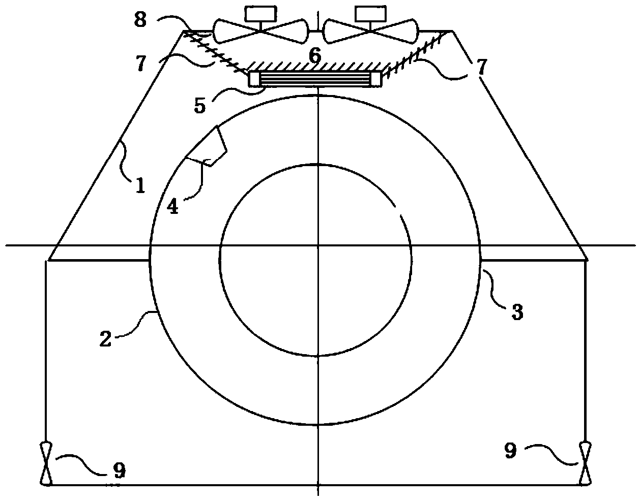
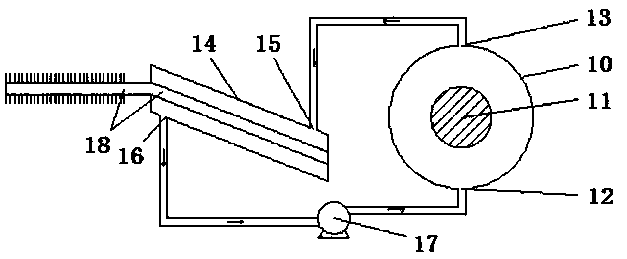
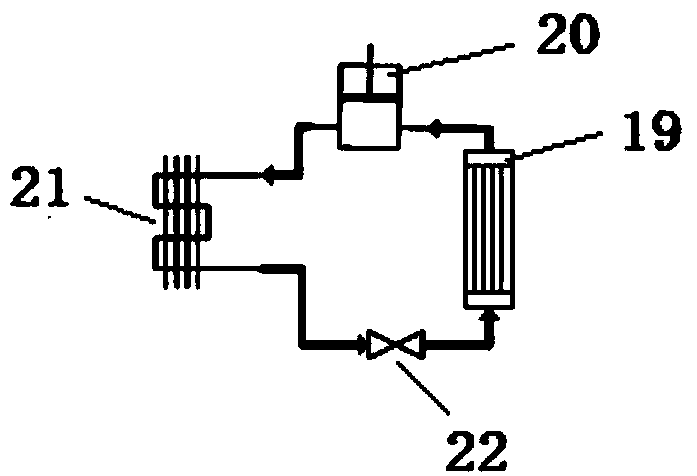
[0036] See Figure 1 ~ Figure 3 , which illustrates the dual cooling system of an X-ray machine according to an embodiment of the present invention, comprising: an inner hollow housing 1; an annular housing 2 located inside the housing 1, which is provided with a cavity, and the annular housing 2 The outer surface is provided with a plurality of vents for heat dissipation at intervals; the bracket 3 is fixed on the inner side of the housing 1 for supporting and fixing the annular housing 2; the liquid cooling system 4 of the X-ray tube is connected with the X-ray tube 11 Commonly fixed in the cavity of the annular housing 2, the liquid cooling system 4 of the X-ray tube and the X-ray tube 11 rotate around the axis of the annular housing 2; the pre-cooling system 5, its functi...


PUM


Abstract

The invention discloses a double cooling system of an X-ray machine. The double cooling system comprises a shell, an annular shell, a support, a liquid cooling system of an X-ray tube, a pre-cooling system, a first air door, second air doors, air supply motors and exhaust motors. The air supply motors, the first air door, the pre-cooling system, the liquid cooling system of the X-ray tube and the exhaust motors form a first cooling system. The air supply motors, the second air doors and the exhaust motors form a second cooling system. On the basis that cost and system complexity are not increased obviously, the advantages of an air cooling system and the liquid cooling system are integrated. When the quantity demanded for cooling loads is large, the liquid cooling system is preferentially used, or the two systems are used at the same time. When the quantity demanded for the cooling loads is small, the air cooling system is preferentially used. When one cooling system fails, the other system can be standby, so that normal and continuous operation of the X-ray machine is guaranteed, and the machine halt time is significantly reduced.

Description

technical field [0001] The invention relates to a medical device, in particular to a double cooling system for cooling an X-ray tube on an X-ray machine. Background technique [0002] Nearly 100% of the energy used to generate X-rays in an X-ray tube is converted into heat. Due to the huge heat generation, the existing X-ray tube cooling system is usually a liquid (such as oil, etc.) cooling system, that is, the cooling medium passes between the X-ray tube and the supporting housing of the X-ray tube to absorb the heat, and The heated liquid cooling medium is transported to the air cooler outside the X-ray tube through the coolant pump and the pipeline, and the liquid cooling medium is cooled by the wind and then transported back to the support housing of the X-ray tube. The X-ray tube cooling system is generally fixed on the X-ray machine bracket together with the X-ray tube, and rotates around a certain rotation axis. [0003] The X-ray tube cooling system includes an ai...

Claims


Application Information

Patent Timeline
Patent Type & Authority Applications(China)
IPC IPC(8): F25B1/00F25B41/06A61B6/00H01J35/02F25B41/30
Inventor 范韶锋刘翔周锐
Owner MING WEI MEDICAL TECH SUZHOU
Why Eureka
Try Eureka