Electromagnetic resonance control circuit, electromagnetic heating device and method for controlling transistor

A resonant circuit and control circuit technology, applied in the direction of induction heating, induction heating control, etc., can solve the problems of IGBT damage and easily damaged IGBT, and achieve the effect of prolonging the opening time, prolonging the service life and avoiding damage

Active Publication Date: 2014-04-30
MIDEA GRP CO LTD +1
View PDF6 Cites 17 Cited by
  • Summary
  • Abstract
  • Description
  • Claims
  • Application Information

AI Technical Summary

Problems solved by technology

[0003] Since the rectified voltage of the mains still changes with time (that is, the half cycle of the sine wave), but in related technologies, the IGBT maintains the same turn-on time in the rectified envelope of the mains, Therefore, when the input voltage to the resonant circuit is high, and the peak voltage and peak current at resonance are large, a large peak current will flow through the IGBT when it is turned on, and it will also withstand high feedback after the IGBT is turned off. to the voltage, but the peak voltage and peak current are too high to easily damage the IGBT
[0004] Therefore, how to control the turn-on time of the IGBT according to the voltage input to the resonant circuit, so as to control the peak voltage and peak current of the resonant circuit, and avoid damage to the IGBT due to the large peak voltage and peak current has become a technical problem to be solved urgently.

Method used


Image

  • Electromagnetic resonance control circuit, electromagnetic heating device and method for controlling transistor
  • Electromagnetic resonance control circuit, electromagnetic heating device and method for controlling transistor
  • Electromagnetic resonance control circuit, electromagnetic heating device and method for controlling transistor

Examples


Embodiment Construction

[0044] In order to understand the above-mentioned purpose, features and advantages of the present invention more clearly, the present invention will be further described in detail below in conjunction with the accompanying drawings and specific embodiments. It should be noted that, in the case of no conflict, the embodiments of the present application and the features in the embodiments can be combined with each other.

[0045] In the following description, many specific details are set forth in order to fully understand the present invention. However, the present invention can also be implemented in other ways different from those described here. Therefore, the protection scope of the present invention is not limited by the specific details disclosed below. EXAMPLE LIMITATIONS.

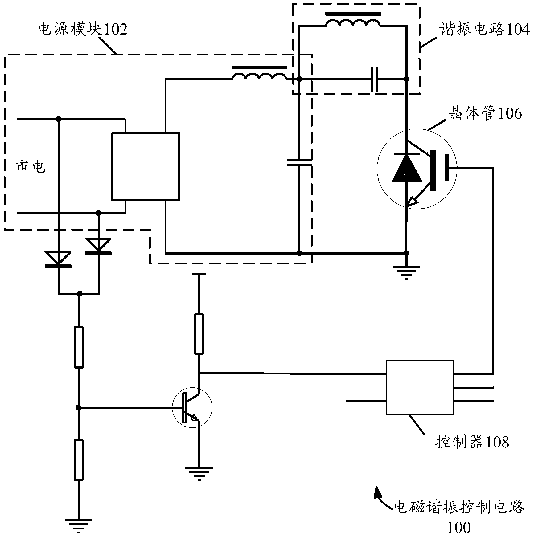
[0046] figure 1 A schematic circuit structure diagram of an electromagnetic resonance control circuit according to an embodiment of the present invention is shown.

[0047] Such as figure 1 As sho...


PUM


Abstract

The invention provides an electromagnetic resonance control circuit, an electromagnetic heating device and a method for controlling a transistor. The electromagnetic resonance control circuit comprises a power module, a resonance circuit, the transistor and a controller, the resonance circuit is connected to the power module, the transistor is arranged between the resonance circuit and the ground, and used for executing the power-on or power-off operation according to pulse width modulation signals sent by the controller to control the work state of the resonance circuit, and the controller is connected to the power module and the control end of the transistor, and used for adjusting the duty ratio of the pulse width modulation signals sent to the transistor according to the change condition of voltages output to the resonance circuit by the power module to control the power-on time of the transistor. According to the technical scheme, the power-on time of the transistor can be controlled according to the voltages output to the resonance circuit, power output is increased in a low-voltage area, power output is reduced in a high-voltage area, the peak voltage and the peak current of the transistor are reduced under the condition of identical power, and therefore the transistor is effectively protected.

Description

technical field [0001] The invention relates to the technical field of electrical appliances with electromagnetic induction, and in particular, relates to an electromagnetic resonance control circuit, an electromagnetic heating device and a control method for a transistor. Background technique [0002] At present, the resonant circuit in the induction cooker is controlled by a transistor, for example, the charge and discharge process of the resonant circuit is controlled by an IGBT (Insulated Gate Bipolar Transistor, insulated gate bipolar transistor). [0003] Since the rectified voltage of the mains still changes with time (that is, the half cycle of the sine wave), but in related technologies, the IGBT maintains the same turn-on time in the rectified envelope of the mains, Therefore, when the input voltage to the resonant circuit is high, and the peak voltage and peak current at resonance are large, a large peak current will flow through the IGBT when it is turned on, and...

Claims


Application Information

Patent Timeline
Patent Type & Authority Applications(China)
IPC IPC(8): H05B6/06
Inventor 汪钊陈伟李新峰肖小龙韩平英
Owner MIDEA GRP CO LTD
Why Eureka
Try Eureka