Generating, a highly ionized plasma in a plasma chamber

A plasma, highly ionized technology, applied in the field of ions, which can solve problems such as reducing membrane adhesion and target poisoning

Active Publication Date: 2014-04-30
TRUMPF HUETTINGER
View PDF4 Cites 6 Cited by
  • Summary
  • Abstract
  • Description
  • Claims
  • Application Information

AI Technical Summary

Problems solved by technology

[0003] However, high power discharge pulses combined with an upstream low ionization step have been found to reduc

Method used


Image

  • Generating, a highly ionized plasma in a plasma chamber
  • Generating, a highly ionized plasma in a plasma chamber
  • Generating, a highly ionized plasma in a plasma chamber

Examples


Embodiment Construction

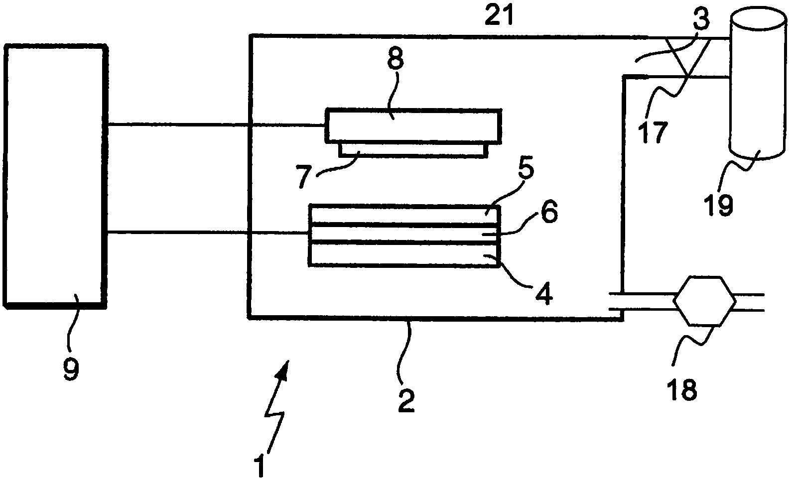
[0102] figure 1 An apparatus 1 suitable for sputtering is shown. The device 1 comprises a plasma chamber 2 with a gas inlet 3 for supplying a neutral gas. The plasma chamber 2 is evacuated by a vacuum pump 18 . The neutral gas to be ionized is admitted from a gas container 19 via a valve 17 .

[0103] Inside the plasma chamber 2 a magnet 4 is provided providing a magnetic field on the surface of a sputtering target 5 . A target 5 is provided on top of an electrode 6 configured as a cathode. Specifically, the target 5 and the cathode 6 are electrically connected. Opposite the target 5, a substrate 7 to be coated with target material is provided. A substrate 7 is provided on the anode 8 . The anode 8 and the cathode 6 are connected to a high-energy pulse power supply 9 to apply a voltage pulse between the anode 8 and the cathode 6 in the plasma chamber 2 . The high-energy pulsed power supply 9 can be controlled to generate pulses to generate a highly ionized plasma from ...


PUM


Abstract

A method of generating a highly ionized plasma in a plasma chamber (2), comprises the steps of: a. providing a neutral gas to be ionized in the plasma chamber (2) at pressure below 50 Pa, b. supplying at least one high energy high power electrical pulse with power equal or larger than 100 kW and energy equal or larger than 10 J, to at least one magnetron cathode in connection with a target in the plasma chamber (2), c. producing a highly ionized plasma directly from the neutral gas in a plasma volume such that the plasma volume cross section increases during a current rise period, d. sputtering atoms from the target with the highly ionized plasma, e. ionizing at least part of the sputtered atoms.

Description

technical field [0001] The present disclosure relates to generating a highly ionized plasma within a plasma chamber. Background technique [0002] In a typical sputter coating process, electrons generated by the discharge collide with the sputtering gas, thereby ionizing the gas. This sputtering process is typically in a pressure range between 10 Pa and 0.1 Pa. In this pressure range, the number of atoms or molecules is 5*10 15 cm -3 and 2*10 13 cm -3 between. As the ions bombard the target, atoms are detached from the target which will deposit on the substrate to be coated. The process of separating the atoms from the target is called the sputtering process. Etching can also be performed using this sputtering process. In some systems, improved target utilization and coating uniformity can be achieved by generating a highly ionized plasma near the target. In such systems, a partially ionized plasma is first generated at a low pressure, followed by a highly ionized p...

Claims


Application Information

Patent Timeline
IPC IPC(8): H01J37/34C23C14/34
CPCH01J37/3405C23C14/46C23C14/34H01J37/34
Inventor A·克利梅扎克P·奥济梅克R·布吉
Owner TRUMPF HUETTINGER
Why Eureka
Try Eureka