Ammonia-flue gas uniformly mixing device

A flue gas and mixer technology, which is applied in the field of flue gas purification, can solve the problems of uneven flow field downstream of the mixer, large deviation of flue gas velocity, etc., and achieve high energy utilization efficiency, shorten distance, and reduce flow field disturbance Effect

Active Publication Date: 2014-05-07
ZHEJIANG UNIV
View PDF9 Cites 12 Cited by
  • Summary
  • Abstract
  • Description
  • Claims
  • Application Information

AI Technical Summary

Problems solved by technology

Because the static mixer adopts a larger mixer plate, and the mixer plates are all inclined to the same direction, the flow field downstream of the mixer is not uniform, so that the velocity deviation of the flue gas at the entrance of the SCR reactor is still large

Method used


Image

  • Ammonia-flue gas uniformly mixing device
  • Ammonia-flue gas uniformly mixing device
  • Ammonia-flue gas uniformly mixing device

Examples


Embodiment 1

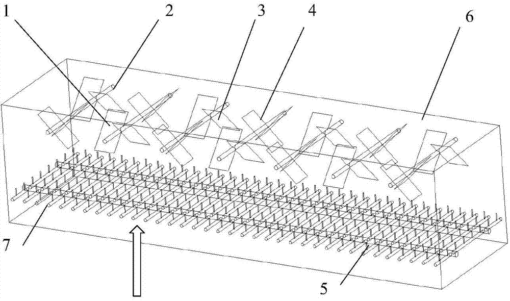
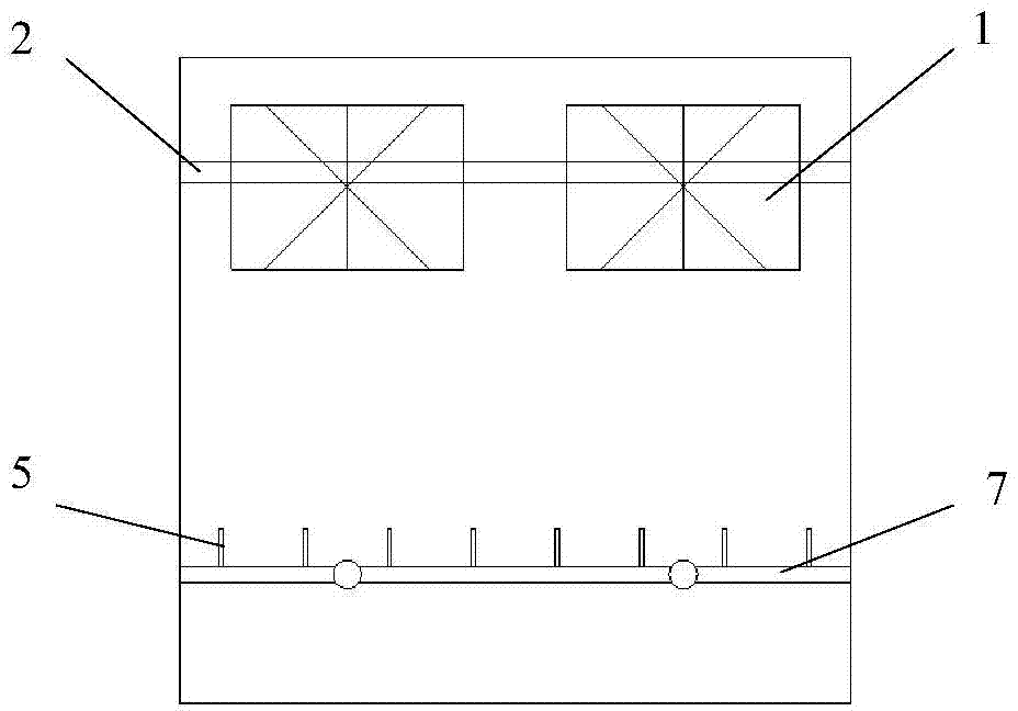
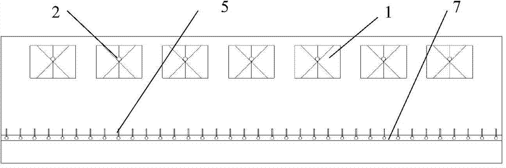
[0031] Such as figure 1 , figure 2 , image 3 As shown, the ammonia-flue gas homogenizing device (hereinafter referred to as the homogenizing device) used in the SCR flue gas denitrification system of a thermal power plant includes 3.5 sets of static mixers 1, each of which consists of 4 mixer units 3 Each mixer unit consists of two intersecting mixing plate blades 4. The mixing plate blade 4 of the mixer unit is fixed in the flue 6 through the support rod 2, the two ends of the support rod are fixed on the side wall of the flue, and two mixer units are fixed on each support rod. figure 1 In the figure, below the homogenizing device is the ammonia injection grid of the SCR flue gas denitrification system, and the ammonia injection grid is composed of the ammonia injection branch pipe 5 and the ammonia injection main pipe 7 connected with the ammonia injection branch pipe. The coverage rate of the static mixer 1 on the horizontal cross-section of the flue is 31.1%. The mixe...

Embodiment 2

[0043] Apply the homogenizing device in the present invention to another thermal power plant SCR flue gas denitrification system, including 3 groups of static mixers, each group of static mixers includes 4 static mixer units, and each static mixer unit includes 2 Composition of mixing plate blades. The fixing method of the blade of the mixing plate is the same as that of Example 1. Due to the short mixing distance between ammonia and flue gas in this SCR system, the static mixer used has a high coverage rate of 59.6% on the horizontal cross-section of the flue, and the mixer unit has an aspect ratio of 1.5:1 The rectangular mixing plate blades are arranged crosswise, and the mixing plate blades form an angle of 60° with the flue gas flow direction. The homogenizing device is arranged 3.0 m above the ammonia injection grid of the SCR flue gas denitrification system.

[0044] Through modeling and numerical simulation calculations, the relative velocity deviation Cv=7.3% at the ...

Embodiment 3

[0047] This homogenizing device is used in the SCR flue gas denitrification system of another thermal power plant, including 2.5 groups of static mixers, each group of static mixers is also composed of 4 static mixing units, and each static mixer unit consists of two length and width Mixing plate blades with a ratio of 2.4:1 are arranged crosswise, and the mixing plate blades form an included angle of 30° with the flue gas flow direction. The installation method is similar to that of Embodiment 1 and Embodiment 2 and fixed in the flue. The coverage rate of the static mixer on the horizontal cross-section of the flue is 21.2%, and the mixer is located 2.0m above the ammonia injection grid of the SCR flue gas denitrification system.

[0048] Through the modeling of the SCR flue gas denitrification system and the simulation calculation results, it can be seen that although the coverage of the static mixer is low and the blade size is relatively small, the relative concentration de...


PUM


Abstract

The invention relates to the technical field of flue gas purification, and particularly relates to an ammonia-flue gas uniformly mixing device. The ammonia-flue gas uniformly mixing device comprises at least one group of static mixers installed in a flue; each group of static mixers consists of four mixer units; each mixer unit consists of two crossed mixing plate blades which form an included angle of 30 degrees-60 degrees relative to the flowing direction of flue gas. When the flue gas passes each group of static mixers, besides the partial eddy formed by each mixing plate blade, four adjacent mixing plate blades in the center form anticlockwise (or clockwise) eddy flow, and four mixing plate blades at the outer periphery generate opposite eddy flow at the opposite direction, so that double eddy flows at different directions are formed at the flow direction of flue gas; the double eddy flows at opposite directions are mixed fiercely, the mixing process is intensified, so that ammonia is distributed uniformly; meanwhile, the distance required for the aim of ammonia uniformity is shortened; the denitrification efficiency is improved; the caused pressure drop is small, and the energy utilization ratio is high.

Description

technical field [0001] The invention relates to the technical field of flue gas purification, in particular to an ammonia-flue gas homogeneous mixing device. Background technique [0002] With the increasingly prominent environmental problems, nitrogen oxides have become one of the main control targets of air pollution emissions in my country. Selective catalytic reduction technology (SCR) has become the first choice for flue gas denitrification technology due to its mature process, reliable operation and high denitrification efficiency. The selective catalytic reduction technology is to send the reducing agent ammonia into the flue through the ammonia pipe, mix with the flue gas in the flue, and then under the action of the catalyst, the reducing agent ammonia selectively reacts with the NO in the flue gas. x reacted, the NO x reduced to N 2 , while generating H 2 O. The existing SCR flue gas denitrification system has a very compact flue arrangement, which leads to un...

Claims


Application Information

Patent Timeline
Patent Type & Authority Applications(China)
IPC IPC(8): B01D53/90B01D53/56B01F5/06
Inventor 高翔骆仲泱岑可法倪明江张成健吴卫红宋浩赵健施正伦周劲松
Owner ZHEJIANG UNIV
Why Eureka
Try Eureka