Vertical water-stop structure for concrete engineering expansion joint as well as manufacturing and construction methods for same

A vertical water-stop and concrete technology, applied in underwater structures, marine engineering, earthwork drilling and other directions, can solve the problems of prolonged construction period, irregular deformation of concrete grooves, difficult to clean, etc., to reduce construction period, save installation process, The effect of preventing the misalignment of the cross-section interface

Inactive Publication Date: 2014-05-07
福建九鼎建设集团有限公司
View PDF7 Cites 53 Cited by
  • Summary
  • Abstract
  • Description
  • Claims
  • Application Information

AI Technical Summary

Problems solved by technology

[0002] In existing concrete structures, such as retaining dams, reservoirs, subways, culverts, sluices, tunnels and other underground projects, due to the inability to pour continuously or the deformation of the foundation settlement (earthquake), or the concrete caused by temperature changes Due to thermal expansion and contraction of components, deformation joints and construction joints are often left during pouring. These gaps must take anti-leakage measures to prevent external water or groundwater from leaking into the structural space. Concrete grooves are set between the concrete and the second-stage concrete, and soft asphalt and copper sheets or rubber waterstops are installed in the grooves. However, this method requires prefabricated concrete grooves. The outer 3 sides are chiseled, which will prolong the construction period and increase labor. At the same time, because the length (height) of each concrete groove is generally only 50-100cm, the expansion gap must be composed of multiple concrete grooves, so multiple horizontal lines will be generated. The gaps and the irregular deformation of multiple concrete grooves will cause the leakage of soft asphalt in the subsequent pouring, and it is difficult to clean up

Method used


Image

  • Vertical water-stop structure for concrete engineering expansion joint as well as manufacturing and construction methods for same
  • Vertical water-stop structure for concrete engineering expansion joint as well as manufacturing and construction methods for same
  • Vertical water-stop structure for concrete engineering expansion joint as well as manufacturing and construction methods for same

Examples


Embodiment

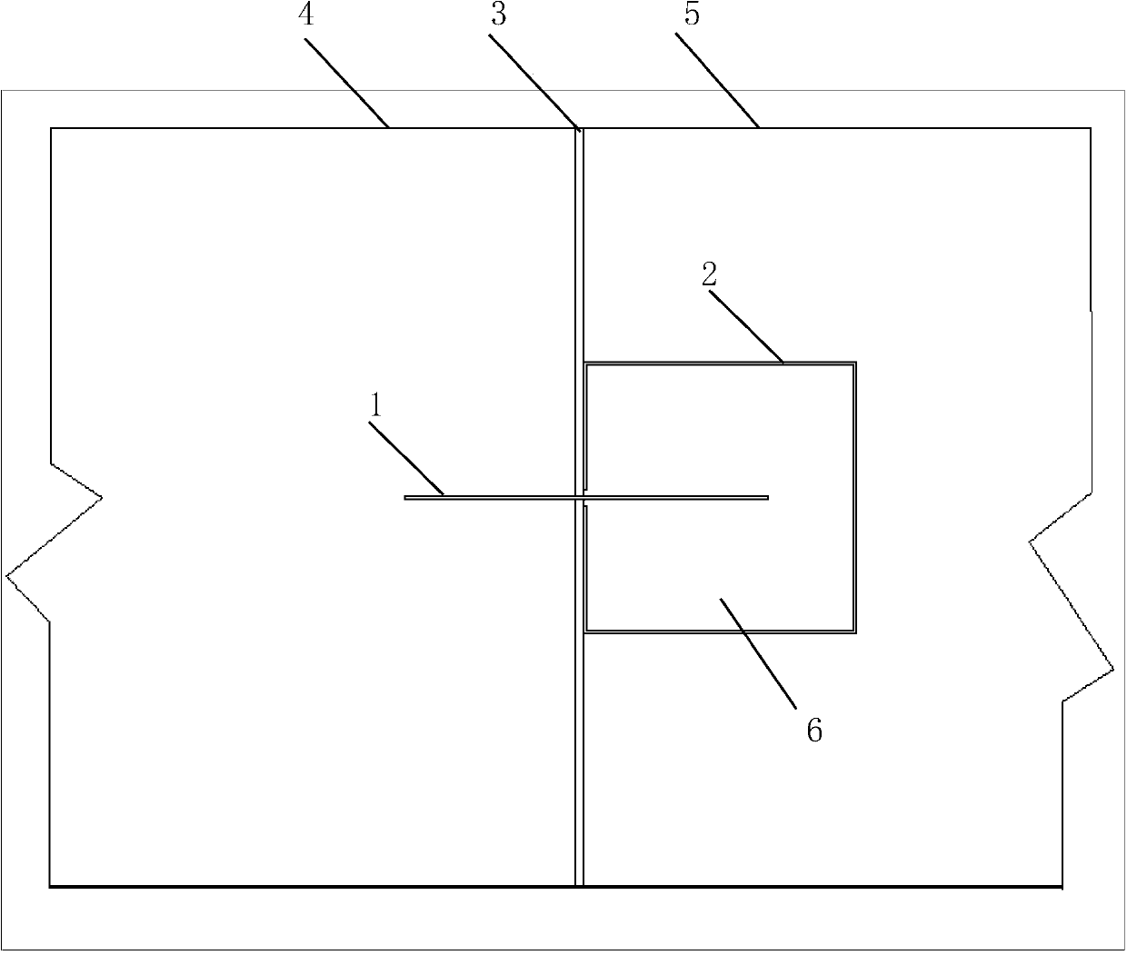
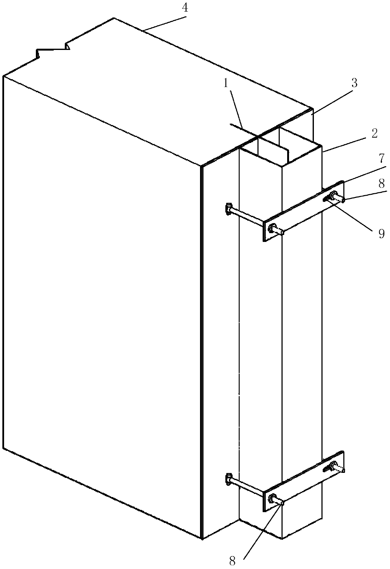
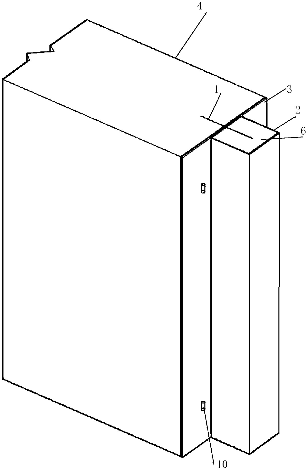
[0045] Embodiment, referring to the accompanying drawings: a vertical water-stop structure for expansion joints in concrete engineering, including a deformation piece 1 and a channel steel 2, the deformation piece 1 is arranged longitudinally, half of which is pre-embedded in the first-stage concrete 4, and the other half protrudes Set outside the concrete section in the rectangular channel steel opening 14, the channel steel 2 is provided with fixing parts, and the channel steel 2 is provided with soft asphalt 6; Linoleum 3 is provided on both sides of sheet 1 .

[0046] Further, the deformable sheet 1 is in the form of a rectangular plate with a width of 30-60 cm and a length equal to the height of the concrete section. The side of the poured concrete is provided with fins 13, and the fins 13 are semicircular. One side is bent at 90°, several fins 13 are set according to the length (height) of the deformation sheet 1, and the deformation sheet 1 is longitudinally arranged in t...


PUM


Abstract

The invention relates to an underground (underwater) building waterproof device, and in particular to a vertical water-stop structure for a concrete engineering expansion joint as well as a manufacturing and construction methods for the same. The vertical water-stop structure comprises a deformation sheet and channel steel, and is characterized in that the deformation sheet is longitudinally arranged, one half is pre-buried in first-stage concrete, the other half is bulged out of a concrete section and externally arranged in a rectangular channel steel opening, and the channel steel is provided with a fixing element and filled with maltha; the surface of the channel steel opening and the section of the first-stage concrete are provided with asphalt felts at the both sides of the deformation sheet, the exposed fixing element is detached after asphalt is cooled, and then second-stage concrete is arranged. According to the vertical water-stop structure disclosed by the invention, the problem of water seepage of a water conservancy project due to the differential settlement or diastrophism of a stratum can be solved, and moreover, labour can be saved and construction period can be shortened.

Description

technical field [0001] The invention relates to an underground (underwater) building waterproof device, in particular to a vertical water-stop structure for expansion joints in concrete engineering and its manufacturing and construction methods. Background technique [0002] In existing concrete structures, such as retaining dams, reservoirs, subways, culverts, sluices, tunnels and other underground projects, due to the inability to pour continuously or the deformation of the foundation settlement (earthquake), or the concrete caused by temperature changes Due to thermal expansion and contraction of components, deformation joints and construction joints are often left during pouring. These gaps must take anti-leakage measures to prevent external water or groundwater from leaking into the structural space. Concrete grooves are set between the concrete and the second-stage concrete, and soft asphalt and copper sheets or rubber waterstops are installed in the grooves. However, ...

Claims


Application Information

Patent Timeline
Patent Type & Authority Applications(China)
IPC IPC(8): E02D31/02E02D29/16E02B3/16E21D11/38
Inventor 张朝利
Owner 福建九鼎建设集团有限公司
Why Eureka
Try Eureka