Reinforcement method for grid structure rod piece

A grid structure and rod technology, which is applied in building construction, building maintenance, construction, etc., can solve problems such as engineering structures that are not suitable for local reinforcement, affecting the stress state of rods, and difficult to meet requirements, and achieve self-stabilization. The effect of good performance, convenient machining, convenient installation and construction

Active Publication Date: 2014-05-07
HUAIHAI INST OF TECH
View PDF8 Cites 10 Cited by
  • Summary
  • Abstract
  • Description
  • Claims
  • Application Information

AI Technical Summary

Problems solved by technology

Welding connections will produce different degrees of welding residual stress. At the same time, the rods are in a local high temperature state, which will seriously affect the stress state of the original rods. Therefore, the requirements for the welding process are relatively high, and it is difficult to meet the requirements
[0010] 3) Change the structural system method: This method has a large workload, time-consuming and labor-intensive, high reinforcement costs, and completely changes the stress state of the original system. There is a large difference between the original rods and the design bearing capacity before and after reinforcement
The stress state of all rods needs to be analyzed, which is not suitable for locally reinforced engineering structures

Method used


Image

  • Reinforcement method for grid structure rod piece
  • Reinforcement method for grid structure rod piece
  • Reinforcement method for grid structure rod piece

Examples


Embodiment Construction

[0030] The specific technical solutions of the present invention are further described below, so that those skilled in the art can further understand the present invention, without limiting their rights.

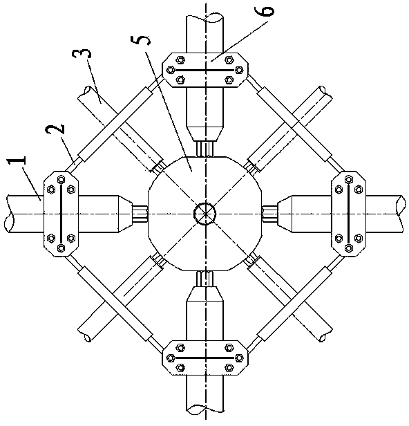
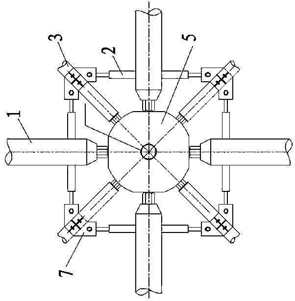
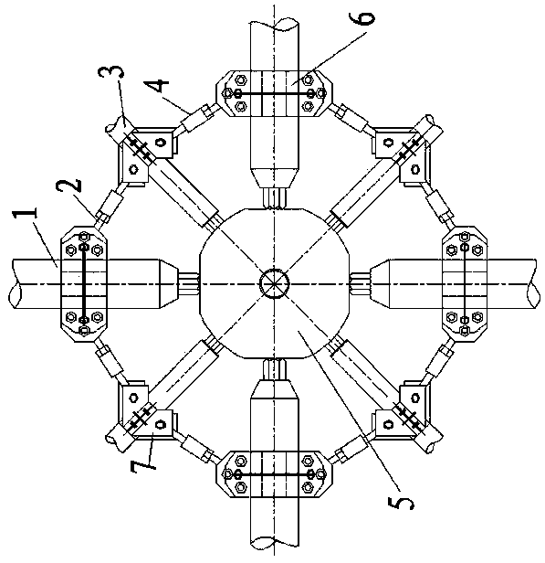
[0031] A reinforcement method for grid structure rods, the steps are as follows: select the compression rods to be reinforced, take the spherical node 5 at the end of the above-mentioned compression rod as the center, and connect the four nodes connected to the above-mentioned spherical nodes 5 The chord 1 is provided with a chord reinforcement frame, and the chord reinforcement frame is composed of four support rods 2 installed between every two adjacent chords 1, and the two ends of each support rod 2 pass through the chord connecting seat 6 It is connected to the chord 1; on the four webs 3 connected to the above-mentioned spherical nodes 5, a web reinforcement frame is provided, and the web reinforcement frame is supported by four webs installed between every two adjacent...


PUM


Abstract

The invention relates to a reinforcement method for a grid structure rod piece, which comprises the following steps that a pressed rod piece which needs to be reinforced is selected, chord member reinforcing frames are arranged on four chord members connected with each spherical joint by using the spherical joint at the end part of the pressed rod piece as the center, each chord member reinforcing frame is formed by four supporting rods arranged between each two adjacent chord members, and both ends of each supporting rod are connected with the corresponding chord members by chord member connecting seats; web member reinforcing frames are arranged on four web members connected with each spherical joint, each web member reinforcing frame is formed by four supporting rods arranged between each two adjacent web members, and both ends of the supporting rod are connected with the corresponding web members by web member connecting seats; and diagonal bars are arranged between each chord member connecting seat and two adjacent web member connecting seats and one reinforcing supporting group is formed by the chord member reinforcing frames, the web member reinforcing frames and the diagonal bars at the position of each spherical joint, so that bearing capacity of the pressure-resistant rod piece is improved.

Description

technical field [0001] The invention relates to a reinforcement method, in particular to a reinforcement method of grid structure rods. Background technique [0002] The rods of the grid structure will bend (when under pressure) or break (when under tension) under excessive stress, and rust will also occur in a corrosive environment. In order to ensure that the overall structure has a continuous The bearing capacity meets the normal use function, and usually the damaged rods are reinforced or replaced. [0003] The method of strengthening the existing grid structure: [0004] 1) Rod replacement method: For the rods that need to be reinforced, when conditions permit, replace the original rods with rods with suitable cross-sections; another way is to add rods at the two nodes . [0005] 2) The method of increasing the section of the bar: the method of increasing the section of the original bar for reinforcement, such as adding steel pipes, angle steel, channel steel, steel...

Claims


Application Information

Patent Timeline
Patent Type & Authority Applications(China)
IPC IPC(8): E04G23/02
Inventor 宋明志王勇姚锦文贺会军胡杰
Owner HUAIHAI INST OF TECH
Why Eureka
Try Eureka