
Eccentric Eddy Current Tuned Mass Damping Device

A technology for tuning mass damping and eccentric mass blocks, which is applied in building components, shock absorbers, and anti-vibration. , the effect of long service life

Active Publication Date: 2015-10-28
QINGDAO CREATE ENVIRONMENT CONTROL TECH +1
View PDF6 Cites 0 Cited by
  • Summary
  • Abstract
  • Description
  • Claims
  • Application Information

AI Technical Summary

Problems solved by technology

However, in the existing TMDs, the dampers are mostly small-hole throttling or hydraulic oil piston-type structures, and the damping ratio of the dampers is fixed. Adjusting the damping ratio can only change the damper. In addition, the damper is in a reciprocating vibration condition. The lower seal is damaged quickly. After the seal is damaged, the pressure difference in the damping chamber cannot maintain the original design, and the damping force drops, so it must be replaced. However, the price of the damper is very high. Relying on the replacement method to solve such problems will inevitably cause great waste
In addition, the stiffness and damping of such products interact with each other, and the parameters are not easy to adjust accurately. Especially once the product is formed, its damping is difficult to adjust later, which seriously affects the vibration reduction effect of TMD products, and also increases the difficulty and cost of later maintenance.
[0003] On the other hand, for some mechanical equipment or building structures, the vibration is not only manifested in vertical vibration or single lateral vibration, but also has torsional vibration or / and multi-directional vibration in the horizontal plane. Existing TMD products cannot Effectively meet the vibration reduction requirements of the above-mentioned complex vibrations

Method used


Image

  • Eccentric Eddy Current Tuned Mass Damping Device
  • Eccentric Eddy Current Tuned Mass Damping Device
  • Eccentric Eddy Current Tuned Mass Damping Device

Examples


Embodiment 1

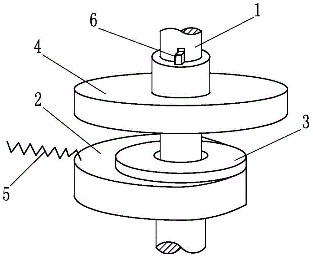
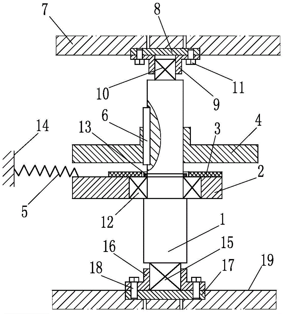
[0042] Such as figure 1 with figure 2 The shown eccentric eddy current tuning mass damping device of the present invention includes a main shaft 1, a spring, an eccentric mass 2, a conductor plate 4 and a permanent magnet 3, the main shaft 1 is arranged through the conductor plate 4 and the permanent magnet 3, and the eccentric mass 2 There is a rotating bearing 12 between the main shaft 1, the conductor plate 4 is fixedly arranged on one side of the eccentric mass 2 perpendicular to the central axis of the main shaft 1, and the permanent magnet 3 is located between the conductor plate 4 and the eccentric mass 2 and fixed by bonding On the eccentric mass 2, there is a gap between the conductor plate 4 and the permanent magnet 3, the spring is specifically a tension spring 5, one end of the tension spring 5 is connected to the eccentric mass 2, and the other end is connected to the surrounding fixed structure 14 Keeping fixed, the conductor plate 4, the permanent magnet 3, th...

Embodiment 2

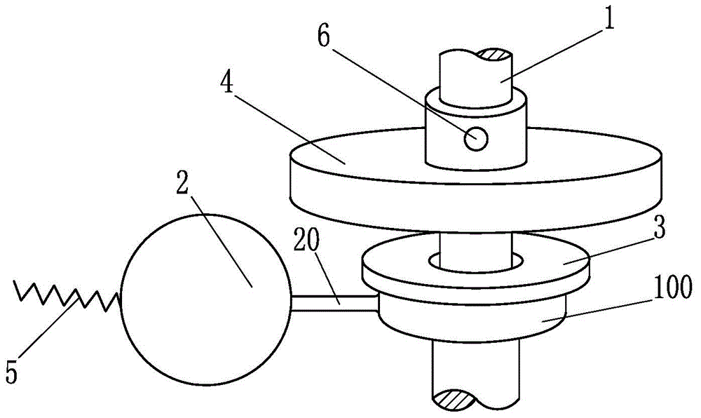
[0057] Such as image 3 , Figure 4 The difference between the eccentric eddy current tuning mass damping device of the present invention and the first embodiment is that the eccentric mass 2 and the main shaft 1 are connected by a straight arm connecting rod structure, and a rotation is set between the straight arm connecting rod structure and the main shaft 1 Bearing 12, the straight arm connecting rod structure is composed of a straight connecting rod 20 and a bearing seat 100, the straight connecting rod 20 is arranged between the eccentric mass 2 and the bearing seat 100, the rotating bearing 12 is arranged in the bearing seat 100, and the rotating bearing Adopt interference fit between 12 and bearing block 100. In addition, a position adjustment structure 6 is provided between the conductor plate 4 and the main shaft 1 , and the position adjustment structure 6 is specifically a screw through hole and a jack screw provided on the conductor plate 4 .

[0058]The applicat...

Embodiment 3

[0060] Such as Figure 5 The difference between the eccentric eddy current tuning mass damping device of the present invention and the second embodiment is that the eccentric mass 2 and the main shaft 1 are connected by a crank arm connecting rod structure, and a rotation is set between the crank arm connecting rod structure and the main shaft 1 bearings. The straight arm connecting rod structure is composed of a curved connecting rod 21 and a bearing seat 100, the curved connecting rod 21 is arranged between the eccentric mass 2 and the bearing seat 100, the rotating bearing 12 is arranged in the bearing seat 100, and the rotating bearing 12 and the bearing An interference fit is adopted between the seats 100 .

[0061] The technical solution described in this example has all the advantages of the technical solution described in Embodiment 2. Compared with Embodiment 2, due to the arrangement of the curved arm connecting rod structure 21, it can overcome the problem of vibra...


PUM


Abstract

The invention belongs to the technical field of building structure vibration attenuation, and particularly relates to a tuned mass damping device utilizing eddy current for providing damping. The tuned mass damping device comprises a conductor plate and a permanent magnet, and is characterized by also comprising a main shaft, a spring and an eccentric mass block, wherein the eccentric mass block is fixedly arranged on the main shaft, or a rotating bearing is arranged between the eccentric mass block and the main shaft, one end of the spring is connected with the eccentric mass block, the conductor plate is fixedly arranged at one side of the eccentric mass block in a direction vertical to an axle line of the main shaft, the permanent magnet is positioned between the conductor plate and the eccentric mass block and is fixedly arranged on the eccentric mass block, a gap is formed between the conductor plate and the permanent magnet, and the conductor plate, the permanent magnet, the main shaft, the spring and the eccentric mass block jointly form a group of eddy current tuned mass damping structures. The eccentric eddy current tuned mass damping device has the advantages that the structure is simple, the practicability is high, safety and reliability are realized, the cost performance is higher, the tuned mass damping device can be widely applied to structure vibration control of various high-rise and super high-rise buildings, drawn-up structures or long-span buildings, and the market application prospects are very wide.

Description

technical field [0001] The invention belongs to the technical field of vibration reduction of building structures, and in particular relates to a tuning mass damping device which utilizes eddy currents to provide damping. Background technique [0002] With the development of urban construction, various high-rise, ultra-high-rise buildings, thin-height structures, and long-span buildings are increasing. At the same time, the urban transportation network is becoming more and more developed. Bridge structures such as trestle bridges have been widely used, bringing great convenience to people's life and travel. However, such thin and tall buildings and bridges are prone to resonance under the excitation of external forces such as strong winds or earthquakes, which will bring uncomfortable feelings to residents or pedestrians, cause structural damage to the structure itself, and even seriously threaten the safety of people and vehicles. . How to prevent such large-span, low-fre...

Claims


Application Information

Patent Timeline
Patent Type & Authority Patents(China)
IPC IPC(8): F16F6/00F16F7/104E04B1/98E01D19/00
Inventor 刘中冬徐建尹学军徐赵东张元刚孟令帅孙召成姜成孔祥斐
Owner QINGDAO CREATE ENVIRONMENT CONTROL TECH
Learn More