
Externally-connected water pipe connecting structure for centrifugal casting machine

A technology of centrifugal casting machine and connecting structure, applied in the direction of hose connection device, adjustable connection, pipe/pipe joint/pipe fitting, etc., can solve the inconvenient replacement of maintenance personnel, production and safety impact, cooling effect and poor casting quality and other problems, to ensure the cooling water flow and casting quality, increase economic benefits, and reduce labor intensity.

Active Publication Date: 2014-05-07
河北新兴铸管有限公司
View PDF4 Cites 5 Cited by
  • Summary
  • Abstract
  • Description
  • Claims
  • Application Information

AI Technical Summary

Problems solved by technology

[0003] The cooling water system of the water-cooled metal mold centrifugal casting machine is mainly provided through the intermediate water pipe connected to the external water source pipe. The connection between the intermediate water pipe and the external water source pipe is fixedly connected by a flange. During the pouring process, the intermediate water pipe also walks with the main machine. A large torsion force is generated with the fixed external water source pipe. In addition, the span between the centrifugal casting machines is very narrow, and the intermediate water pipe cannot adjust the angle with the running of the centrifugal casting machine. With the increase of cast pipe production, the centrifugal casting machine The production pace is accelerated and the machine-hour output is increased. The current large-diameter intermediate water pipe with an outer diameter of Φ152 is often discounted during the process of pulling up and down the centrifugal casting machine, which affects the cooling water flow, resulting in poor cooling effect and casting quality. , or the phenomenon that the flange interface falls off, the service life of the intermediate water pipe is reduced, which has a great impact on production and safety. It is also inconvenient for maintenance personnel to replace at high altitude, which increases the maintenance intensity and workload.

Method used


Image

  • Externally-connected water pipe connecting structure for centrifugal casting machine
  • Externally-connected water pipe connecting structure for centrifugal casting machine

Examples


Embodiment Construction

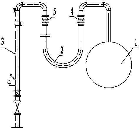
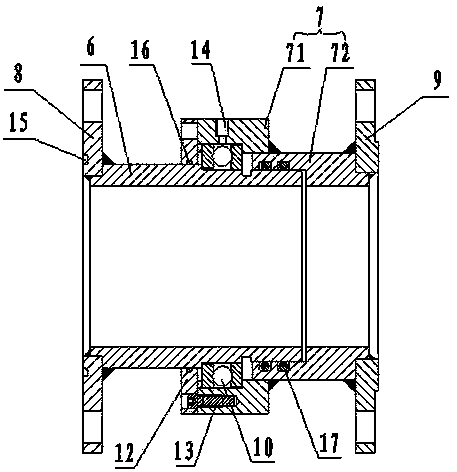
[0016] The present invention will be further described in detail below in conjunction with the accompanying drawings and specific embodiments.

[0017] Such as figure 1 , 2 The shown connection structure of external water pipes of a centrifugal casting machine includes a centrifugal casting machine 1, an intermediate water pipe 2 and a water source pipe 3, and also includes a first sealed rotary joint 4 and a second sealed rotary joint 5. The intermediate water pipe 2 is arranged on Between the water source pipeline 3 and the centrifugal casting machine 1, the first sealed rotary joint 4 is arranged between the water inlet pipe of the centrifugal casting machine 1 and the intermediate water pipe 2, and the second sealed rotary joint 5 is arranged between the intermediate water pipe 2 and the water source pipeline 3 , the intermediate water pipe 2 is a hose. The first sealed rotary joint 4 and the second sealed rotary joint 5 are connected, and the middle water pipe 2 adopts ...


PUM


Abstract

The invention discloses an externally-connected water pipe connecting structure for a centrifugal casting machine and relates to the technical field of equipment accessories of water cooling metal type centrifugal casting machines. The externally-connected water pipe connecting structure for the centrifugal casting machine comprises the centrifugal casting machine, a middle water pipe, a first sealing rotary connector, a second sealing rotary connector and a water source pipeline. The middle water pipeline is arranged between the water source pipeline and the centrifugal casting machine, the first sealing rotary connector is arranged between a water inlet pipe of the centrifugal casting machine and the middle water pipe, the second sealing rotary connector is arranged between the middle water pipe and the water source pipeline, and the middle water pipe is a hose. Due to the fact that the first sealing rotary connector and the second sealing rotary connector are arranged on the connecting portions of the centrifugal casing machine, the middle water pipe and the water source pipeline, in the process of production of the centrifugal casing machine, the angle of the middle water pipe can be freely adjusted, bending and twisting of the middle water pipe can be avoided, the service life of the middle water pipe is prolonged, the operation cost is reduced, the labor intensity of a maintenance person is relieved, and the production efficiency is improved.

Description

technical field [0001] The invention relates to the technical field of accessories for water-cooled metal mold centrifugal casting machines. Background technique [0002] Centrifugal casting is a casting method in which liquid metal is poured into a rotating mold, and the liquid metal fills the mold and solidifies under the action of centrifugal force. The water-cooled metal mold centrifugal casting machine rotates the spheroidized molten iron that meets the requirements at a constant angular speed through the quantitative fan-shaped bag on the casting machine, so that the molten iron flows into the high-speed rotating water-cooled pipe mold along the pouring launder, and casts the molten iron at the same time. The pipe machine moves at a constant speed, and the inner wall of the pipe mold condenses rapidly at the same time to form a cast pipe, and after solidification, the cast pipe is pulled out from the pipe mold. [0003] The cooling water system of the water-cooled met...

Claims


Application Information

Patent Timeline
Patent Type & Authority Applications(China)
IPC IPC(8): F16L27/08
CPCB22D13/10F16L33/18F16L33/28
Inventor 朱传斌孔令松肖玉忠贾耀红
Owner 河北新兴铸管有限公司
Learn More