
Method and system for recycling residual heat of ash and slag of liquid slag-tapping boiler

A technology of liquid slag discharge and boiler ash, which is applied in the field of waste heat recovery and utilization of liquid slag discharge boiler ash and slag, which can solve the problems of large physical heat loss of liquid slag discharge boiler ash and slag, improve thermal buoyancy and diffusion capacity, and weaken corrosion , the effect of saving water resources

Inactive Publication Date: 2014-05-07
XI AN JIAOTONG UNIV
View PDF5 Cites 13 Cited by
  • Summary
  • Abstract
  • Description
  • Claims
  • Application Information

AI Technical Summary

Problems solved by technology

[0008] The purpose of the present invention is to provide a method that can effectively recover the heat of liquid slag, and use it to heat the net flue gas after wet desulfurization, so as to solve the problem of large physical heat loss of liquid slag discharge boiler ash and slag, and at the same time utilize the waste heat of slag discharge Method and system for recovering waste heat from liquid slag discharge boilers by increasing the flue temperature at the chimney inlet, preventing chimney corrosion, improving the thermal buoyancy and diffusion capacity of flue gas, and controlling the phenomenon of "gypsum rain"

Method used


Image

  • Method and system for recycling residual heat of ash and slag of liquid slag-tapping boiler
  • Method and system for recycling residual heat of ash and slag of liquid slag-tapping boiler

Examples


Embodiment 1

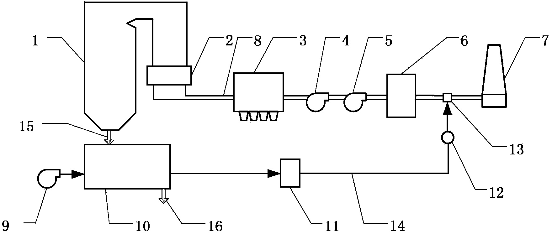
[0027] Embodiment 1: see figure 1 , this embodiment includes a conventional liquid slag discharge boiler, a smoke exhaust system and a liquid slag waste heat recovery and utilization system. Conventional liquid slagging boiler and smoke exhaust system are composed of liquid slagging boiler 1, air preheater 2, dust collector 3, induced draft fan 4, booster fan 5, wet desulfurization equipment 6, chimney 7 and flue 8. The liquid slagging boiler 1 is connected to the flue gas inlet of the air preheater 2 through the flue 8, the flue gas outlet of the air preheater 2 is connected to the flue gas inlet of the dust collector 3, and the flue gas outlet of the dust collector 3 passes through the flue 8 The induced draft fan 4 and the booster fan 5 are connected in sequence, the outlet of the booster fan 5 is connected to the inlet of the wet flue gas desulfurization equipment 6 , and the outlet of the wet flue gas desulfurization equipment 6 is connected to the chimney 7 through the f...

Embodiment 2

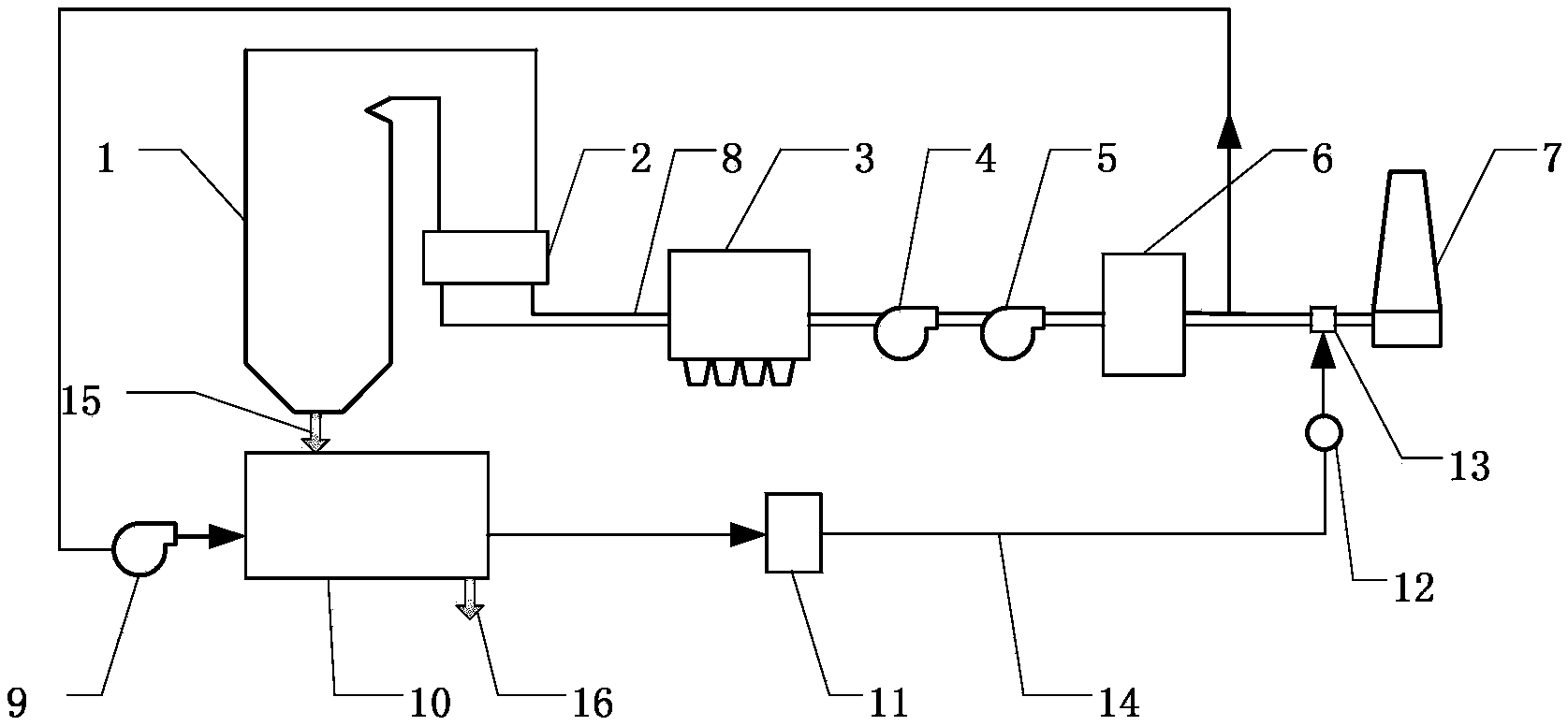
[0029] Example 2: see figure 2, this embodiment includes a conventional liquid slag discharge boiler, a smoke exhaust system and a liquid slag waste heat recovery and utilization system. Conventional liquid slagging boiler and smoke exhaust system are composed of liquid slagging boiler 1, air preheater 2, dust collector 3, induced draft fan 4, booster fan 5, wet desulfurization equipment 6, chimney 7 and flue 8. The flue 8 of the liquid slagging boiler 1 is connected to the flue gas inlet of the air preheater 2 through each heating surface, the flue gas outlet of the air preheater 2 is connected to the flue gas inlet of the dust collector 3, and the flue gas outlet of the dust collector 3 The induced draft fan 4 and the booster fan 5 are sequentially connected through the flue 8 , the outlet of the booster fan 5 is connected to the inlet of the wet flue gas desulfurization device 6 , and the outlet of the wet flue gas desulfurization device 6 is connected to the chimney 7 thr...


PUM


Abstract

The invention discloses a method and a system for recycling the residual heat of ash and slag of a liquid slag-tapping boiler. The method comprises the following steps of by using cold air or partially desulfurized clean smoke gas as a cooling medium, granulating and cooling liquid slag generated by the boiler in a liquid-slag dry-cooling device; sending generated dedusted hot air or hot smoke gas into a flue which is positioned between desulfurizing equipment and a chimney, and mixing and heating the desulfurized clean smoke gas. According to the method, heat in the liquid slag is replaced through the air or the desulfurized smoke gas and is utilized for heating the desulfurized clean smoke gas, so that the heat of the liquid slag can be effectively recycled, the problem of great physical heat loss of the ash and the slag of the liquid slag-tapping boiler is solved, and the economical property of a liquid slag-tapping boiler set is improved. The smoke temperature at the inlet of the chimney is increased by utilizing the residual heat of the liquid slag, so that the chimney can be prevented from being corroded, and the lifting and diffusing capacity of the smoke gas is improved.

Description

technical field [0001] The invention belongs to the field of waste heat recovery and comprehensive utilization, and in particular relates to a method and system for recovery and utilization of ash waste heat of a liquid slag discharge boiler. Background technique [0002] Boilers can be divided into solid slagging boilers and liquid slagging boilers according to the slagging method. In the liquid slag discharge boiler, the ash generated after fuel combustion is discharged in a liquid state. The temperature of the discharged liquid slag is very high, and it must be cooled before it can be comprehensively utilized. At present, most liquid slag discharge boilers use water as the cooling medium to process the liquid slag, that is, the liquid slag is discharged to the granulation through the slag discharge device. In the water tank, the liquid slag is granulated and cooled with slag flushing water, and then the cold slag particles are discharged from the slag removal equipment o...

Claims


Application Information

Patent Timeline
IPC IPC(8): F23J15/08
Inventor 车得福谭晓文白文刚唐春丽吴松
Owner XI AN JIAOTONG UNIV
Learn More