
Cascaded large optical path difference elasto-optic modulation interferometer

A technology of elastic light modulation and optical path difference, which is applied in the field of interferometer, can solve the problem that the interferometer cannot effectively measure weak light, and achieve the effect of easy manufacturing and high luminous flux

Inactive Publication Date: 2016-08-17
ZHONGBEI UNIV
View PDF2 Cites 0 Cited by
  • Summary
  • Abstract
  • Description
  • Claims
  • Application Information

AI Technical Summary

Problems solved by technology

In order to improve the spectral resolution, T N. Buican adopts a series connection method of multiple photoelastic modulation interferometers [see literature: Buican Tudor N, Carrieri Arthur H. Ultra-High Speed ​​Solid-State FTIR Spectroscopy and Applications for Chemical Defense[C].Proceedings for the Army Science Conference (24th), 2004.], but in this structure, the modulated optical path difference and luminous flux are a pair of contradictions. With the increase of the number of reflections, although the optical path difference increases greatly, the corresponding luminous flux also As a result, the entire interferometer cannot effectively measure weak light. Therefore, while increasing the optical path difference, ensuring sufficient luminous flux is the bottleneck problem faced by the elastic optical modulation interferometer.

Method used


Image

  • Cascaded large optical path difference elasto-optic modulation interferometer
  • Cascaded large optical path difference elasto-optic modulation interferometer
  • Cascaded large optical path difference elasto-optic modulation interferometer

Examples


Embodiment Construction

[0029] Further explain the present invention below in conjunction with accompanying drawing description and specific embodiment:

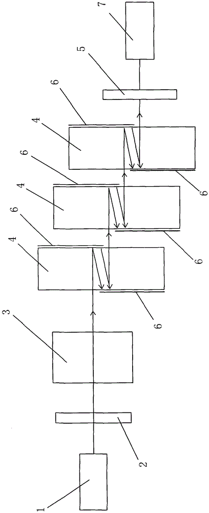
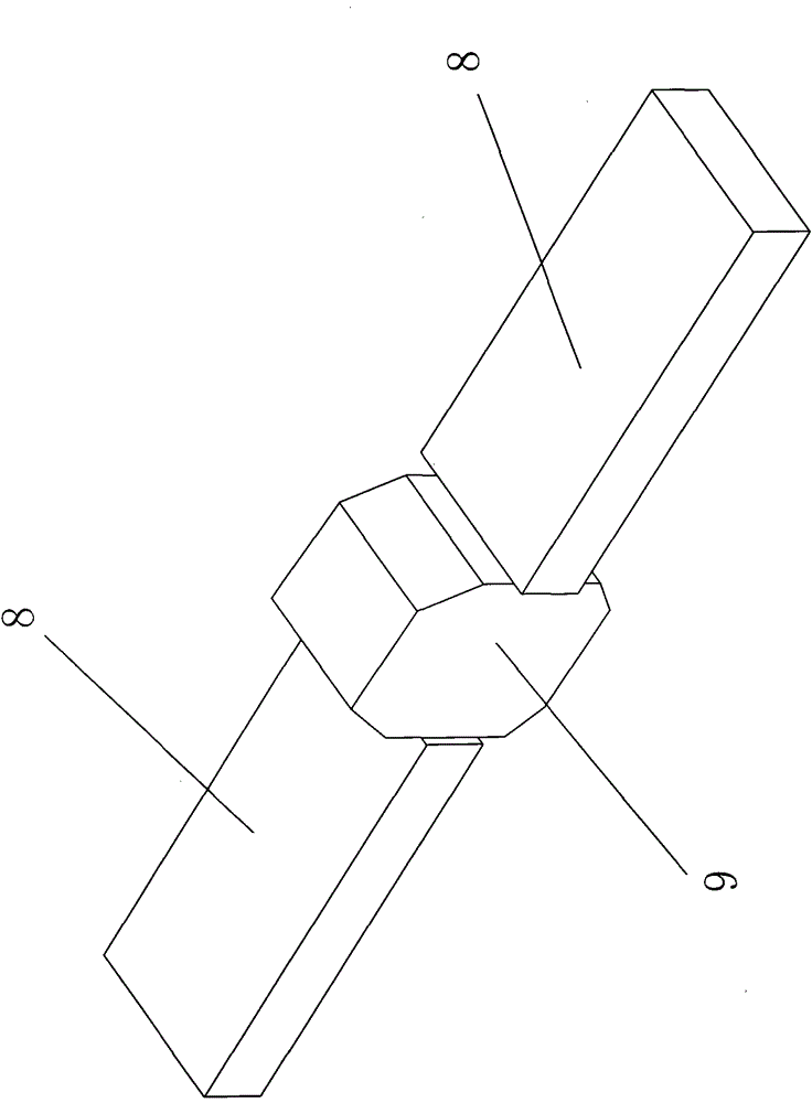
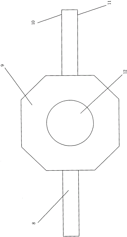
[0030] Such as Figures 1 to 6 As shown, a cascaded large optical path difference elasto-optic modulation interferometer includes a light source 1, and a polarizer capable of modulating the outgoing light to form an angle with the horizontal direction is arranged on the outgoing light direction of the light source 1 2. A static birefringent crystal 3 is provided in the direction of the outgoing light of the polarizer 2, and a plurality of elastic-optical modulators that can cause multiple reflections of the outgoing light are provided in the direction of the outgoing light of the static birefringent crystal 3. An analyzer 4 is provided with an analyzer 5 in the direction of the outgoing light of the elastic optical modulator 4, and a detector 7 capable of collecting light interfered by the analyzer 5 is arranged in the direction of the outgoing lig...


PUM


Abstract

The present invention relates to a cascade large-optical-path-difference photoelastic modulating interferometer which comprises a light source. A polarizer which modulates emergent light to a certain direction to form an angle with the horizontal direction is arranged in the emergent light direction of the light source. A static birefringent crystal is arranged in the emergent light direction of the polarizer. A plurality of strong light modulators which can make emergent light reflect for a plurality of times are arranged in the emergent light direction of the static birefringent crystal. An analyzer is arranged in the emergent light direction of the strong light modulator. A detector which can acquire interfered light of the analyzer is arranged in the emergent light direction of the analyzer. The cascade large-optical-path photoelastic modulating interferometer generates a periodical driving force through a piezoelectric quartz crystal, and furthermore generates two-dimensional coupling longitudinal oscillation by means of a contour oscillation mode of zinc selenide crystal for obtaining higher modulation optical path difference. Based on a fact that a single photoelastic modulator realizes higher modulation optical path difference, the modulation optical path difference is furthermore increased through a cascade manner, thereby settling a problem of small modulation optical path difference in the existing photoelastic modulating interferometer and ensuring enough light flux.

Description

Technical field: [0001] The invention relates to an interferometer, in particular to an elastic-optical modulation interferometer capable of producing a relatively large modulation optical path difference and ensuring sufficient luminous flux. technical background: [0002] The basic principle of the elastic optical modulation interferometer is that when polarized light passes through the elastic optical modulation interferometer, two beams of o light and e light with perpendicular polarization directions are generated, and the modulated optical path difference between these two light waves is proportional to the variable crystal material. Refractive index difference, optical path difference is x=1Δn Michelson interferometer is x=nΔ1, the optical path difference changes half a cycle under the drive of electric signal, and a spectrum measurement is completed. The Los Alamos National Laboratory in the United States was engaged in the early research of related technologies [see...

Claims


Application Information

Patent Timeline
Patent Type & Authority Patents(China)
IPC IPC(8): G01J3/45
Inventor 陈友华张记龙王艳超魏海潮张瑞王立福黄艳飞王志斌张敏娟
Owner ZHONGBEI UNIV
Learn More