
Non-refrigeration infrared focal plane array detector of double-layer structure

A focal plane array and uncooled infrared technology, which is applied in the direction of electric radiation detectors, instruments, measuring devices, etc., can solve the problems of small thermal resistance of single-layer detector structure, reduction of effective infrared absorption area, reduction of filling ratio, etc. , to achieve the effect of increasing the effective absorption area, improving the detection performance and reducing heat loss

Inactive Publication Date: 2014-05-07
WUHAN GAOXIN TECH
View PDF6 Cites 30 Cited by
  • Summary
  • Abstract
  • Description
  • Claims
  • Application Information

AI Technical Summary

Problems solved by technology

For a single-layer detector structure, the bridge legs are folded back on both sides or even around the bridge deck layer, which reduces the filling ratio of each unit, reduces its effective infrared absorption area, and makes it difficult to obtain a lower NETD
[0013] The company applied for patent 201110120925.6 in 2011, and the name is "an uncooled infrared focal plane array detector". There are problems: the thermal resistance of the single-layer detector structure is not large, and the filling ratio is not as high as that of the double-layer detector.

Method used


Image

  • Non-refrigeration infrared focal plane array detector of double-layer structure
  • Non-refrigeration infrared focal plane array detector of double-layer structure
  • Non-refrigeration infrared focal plane array detector of double-layer structure

Examples


Embodiment Construction

[0037] The present invention will be further described in conjunction with the accompanying drawings.

[0038] The purpose and technical solutions of the present invention will be described in detail below in conjunction with specific examples.

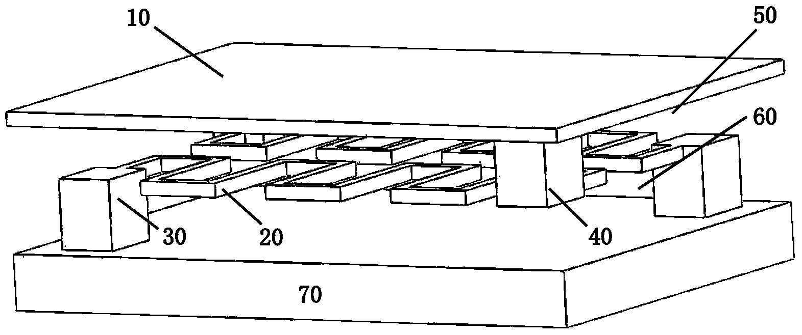
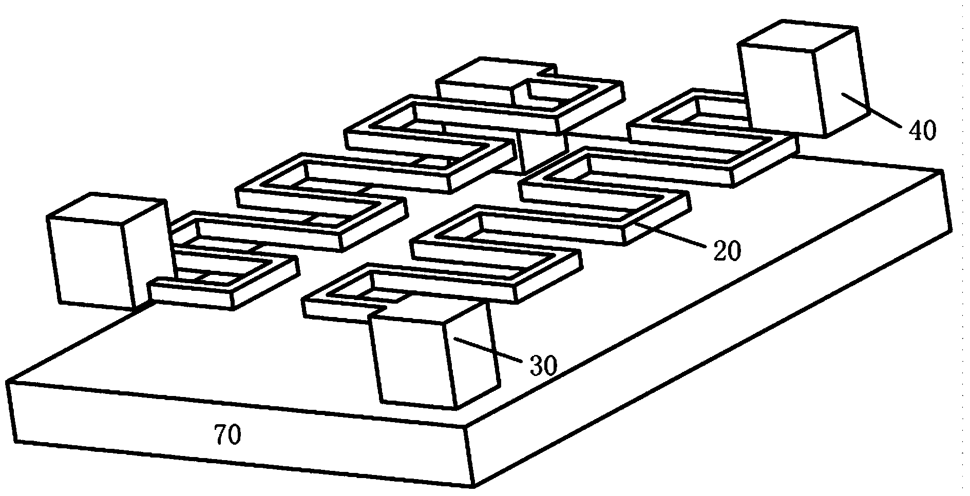
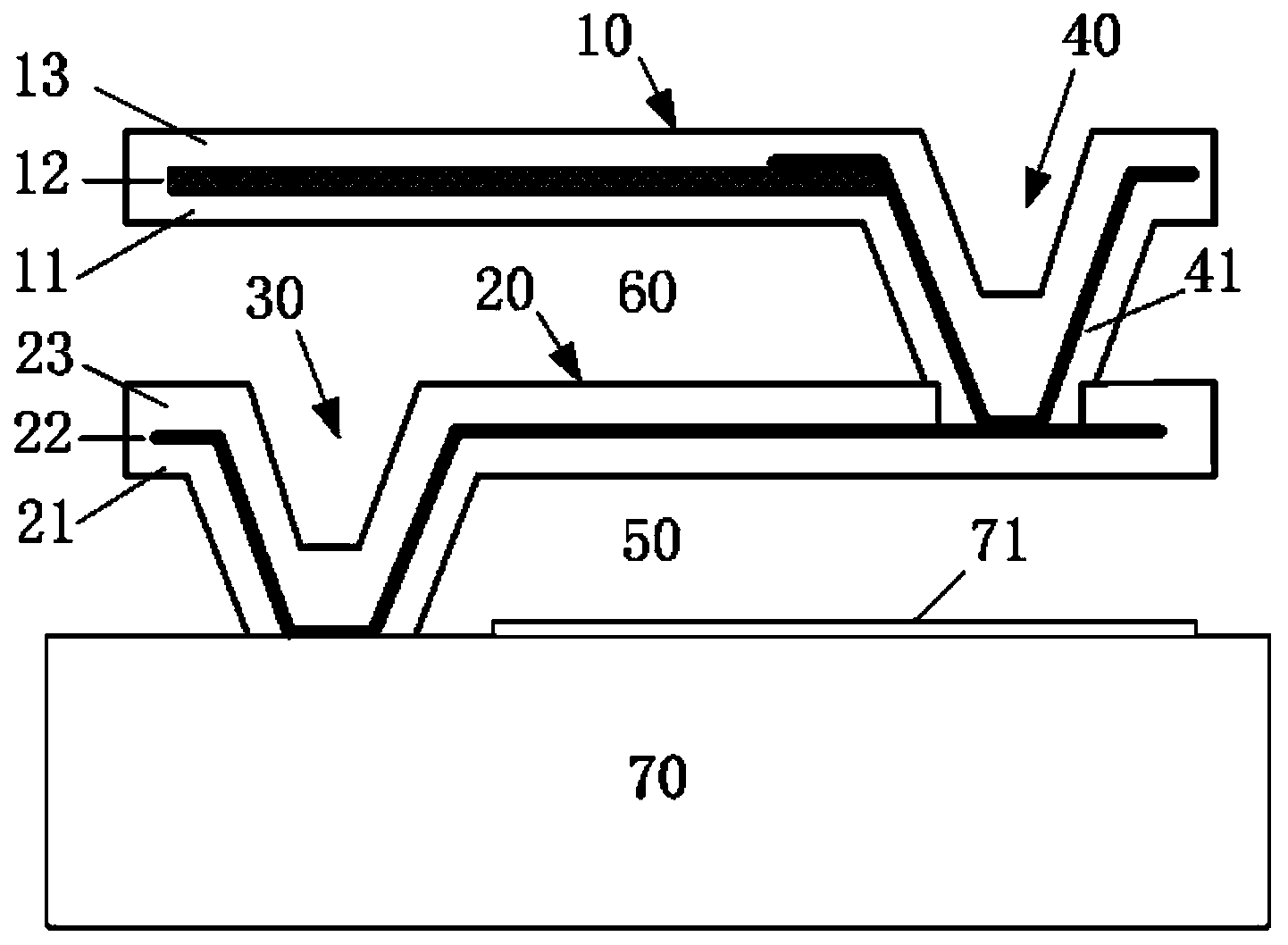
[0039] Such as figure 1 , figure 2As shown, the detector of the present invention is made up of substrate 70, bridge deck layer 10, and two bridge leg layers 20, and each unit composed of substrate 70, bridge deck layer 10, and each bridge leg layer 10 is a double layer Structure: the upper bridge deck layer 10 and the lower bridge leg layer 20; the bridge deck layer 10 is composed of an infrared heat radiation absorbing layer 11 and a heat sensitive layer 12; each bridge leg layer 20 is composed of a support layer 21 and a metal conductive layer 22 Composition; the bridge deck layer 10 and the bridge leg layer 20 are located on the upper and lower planes parallel to each other and are fixedly connected by an electrical conduction ...


PUM


Abstract

The invention relates to a non-refrigeration infrared focal plane array detector of a double-layer structure. The non-refrigeration infrared focal plane array detector of the double-layer structure is composed of a substrate, a bridge floor layer and at least one bridge leg layer and is of the double-layer structure comprises an upper-layer bridge floor layer and a lower-layer bridge floor layer. The bridge floor layer is composed of an infrared thermal radiation absorption layer and a heat reactive layer. The bridge leg layer is composed of a supporting layer and a metal conductive layer. The bridge floor layer and the bridge leg layer are located on the upper plane and the lower plane which are mutually parallel and are fixedly connected through an electrical conduction anchor post. The bridge leg layer is suspended above the substrate and is connected to the substrate through the other electrical conduction anchor post. The substrate is a reading integrated circuit substrate, and the infrared radiation absorption layer is arranged on the surface of the substrate. The non-refrigeration infrared focal plane array detector is obtained through the double-layer structure, the stuffing efficiency of a detector unit can be effectively improved, absorption of infrared thermal radiation is enhanced, the heat insulation capacity of the detector can be effectively improved through a broken line bridge leg structure, the heat loss is reduced, and the overall detection performance is improved.

Description

technical field [0001] The invention relates to an uncooled infrared focal plane array detector with a double-layer structure used in the technical field of infrared imaging systems, and the targeted infrared radiation wavelength range is 8-14 μm. Background technique [0002] According to Planck's black body radiation law, any object above absolute zero will emit infrared electromagnetic heat radiation to the outside world. The light wave range of this radiation is about 0.8-1000 μm, which cannot be directly seen by human eyes. At room temperature (300K), the central wavelength of the emission spectrum of black body radiation is just around the 10μm band; and the infrared thermal radiation emitted by the human body and other objects with similar temperatures in the environment, 38% of the energy is concentrated in the wavelength range of 8-14μm, Therefore, this band is more suitable for detection needs in strong sunlight, dark night or bad weather. [0003] Infrared radiat...

Claims


Application Information

Patent Timeline
IPC IPC(8): G01J5/20
CPCG01J5/023G01J5/024
Inventor 黄立王大甲
Owner WUHAN GAOXIN TECH
Learn More