
Micro-distortion welding method of middle groove of scraper conveyer

A scraper conveyor, micro-deformation technology, applied in welding equipment, arc welding equipment, manufacturing tools, etc., can solve the problems of fast cooling speed, low efficiency, large welding restraint stress, etc., to reduce welding material consumption and welding quality. Stable and controlled welding deformation effect

Active Publication Date: 2014-05-14
NINGXIA TIANDI BENNIU IND GRP
View PDF7 Cites 0 Cited by
  • Summary
  • Abstract
  • Description
  • Claims
  • Application Information

AI Technical Summary

Problems solved by technology

At present, the traditional assembly welding method is widely used, that is, after the point butt welding of the baffle plate groove side, the shovel plate groove side, and the middle plate is completed, the bottom sealing plate is assembled. Due to the large size of the middle plate and the bottom plate during actual welding, the structural rigidity is large. Fast cooling rate, large welding restraint stress, high sensitivity to cold cracking
At the same time, the process is cumbersome and the efficiency is low
[0003] For example, the middle groove of a certain type of scraper conveyor is composed of baffle groove side, shovel groove side, middle plate and bottom cover plate. together, then with CO 2 The gas shielded welding method alternately welds the front and back sides to complete the double-sided V weld of the middle plate, and finally assembles the back cover plate to complete the welding of the back cover plate. After long-term use, it is found that this method, in order to ensure the strength of the middle groove, not only the welded joints of the middle plate The groove is large, and it is difficult to control the welding deformation during the welding process, the process is cumbersome and the efficiency is low

Method used


Image

  • Micro-distortion welding method of middle groove of scraper conveyer
  • Micro-distortion welding method of middle groove of scraper conveyer
  • Micro-distortion welding method of middle groove of scraper conveyer

Examples


Embodiment 1

[0017]

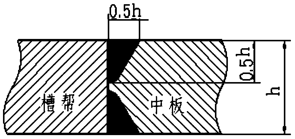
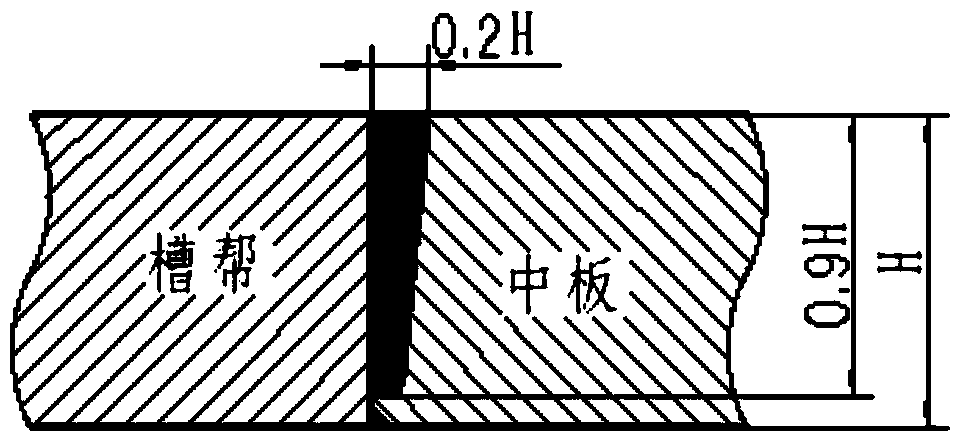
[0018] Firstly, rotate the blade groove side 3 and the baffle groove side 1 by 180 degrees and then reverse them, and assemble the middle plate 2 on the blade groove side 3 and the baffle groove side 1 first, (after installing the middle plate 2, you can install it first , that is, the shovel plate groove side 3 and the baffle plate groove side 1 middle plate 2 are fixed together by welding according to the size requirements of the drawing. Of course, this spot installation step can also be omitted) to complete the back weld of the middle plate 2 with narrow gap MAG welding welding, and then assemble the bottom cover plate 4 to form a box-shaped structure, and then turn the entire box-shaped structure 180 degrees to restore the positive placement of the blade groove side 3 and the baffle groove side 1 (that is, figure 1 The position of the middle groove shown in the figure), and then use narrow-gap MAG welding to weld the front weld seam of the middle plate 2 and th...


PUM


Abstract

The invention relates to a micro-distortion welding method of a middle groove of a scraper conveyer. The micro-distortion welding method is suitable for producing the middle groove of the scraper conveyer of a mining working face of an underground coal mine. The micro-distortion welding method is characterized by including the steps of firstly inversely arranging a shovel plate ledge (3) and a baffle ledge (1), assembling a middle plate (2) on the shovel plate ledge (3) and the baffle ledge (1), meanwhile, completing welding to back welding lines in the middle plate (2) through narrow-gap MAG welding, then assembling a bottom sealing plate (4) to accordingly form a box-type structure, finally overturning the whole box-type structure to enable the shovel plate ledge (3) and the baffle ledge (1) to be placed in the forward direction in a recovered mode, and welding front welding lines in the middle plate (2) and welding lines in the bottom sealing plate (4) through narrow-gap MAG welding. The micro-distortion welding method is efficient and can be used for manufacturing the middle groove of the scraper conveyer under the coal mine, traditional assembling and welding technological processes of the middle groove are effectively changed during welding, and the welding distortion is effectively controlled.

Description

technical field [0001] The invention relates to a micro-deformation welding method for a middle groove of a scraper conveyor, which is suitable for producing the middle groove of a scraper conveyor in an underground mining face of a coal mine. Background technique [0002] The middle trough of the scraper conveyor is welded by the side of the baffle plate, the side of the shovel plate, the middle plate and the bottom plate of the bottom cover. It is used to transport coal and materials. The coal and materials are dragged and slid to the unloading end by the scraper chain. At present, the traditional assembly welding method is widely used, that is, after the point butt welding of the baffle plate groove side, the shovel plate groove side, and the middle plate is completed, the bottom sealing plate is assembled. Due to the large size of the middle plate and the bottom plate during actual welding, the structural rigidity is large. The cooling rate is fast, the welding restraint...

Claims


Application Information

Patent Timeline
Patent Type & Authority Applications(China)
IPC IPC(8): B23K9/16
CPCB23K9/173
Inventor 彭春涛宋智丽李庆平董曼淑
Owner NINGXIA TIANDI BENNIU IND GRP
Learn More