Submarine pipeline trenching machine and trenching method thereof

A technology for submarine pipelines and trenchers, which is applied in the direction of earth movers/shovels, construction, etc., can solve the problems of ineffective soil transportation, reduce the service life of the liquefaction device, increase the wear of the liquefaction device, etc. The speed of silting and firming, reducing wear and improving the degree of liquefaction

Active Publication Date: 2016-08-03
CHINA PETROLEUM & CHEM CORP +1
View PDF6 Cites 0 Cited by
  • Summary
  • Abstract
  • Description
  • Claims
  • Application Information

AI Technical Summary

Problems solved by technology

For complex seabed geological conditions, only one method of soil liquefaction or crushing cannot effectively liquefy or crush all kinds of soil, so it cannot effectively realize the transportation of soil
In addition, the outlet of the trenching machine conveying device at home and abroad is open, and the discharged sediment is easy to return to the entrance of the liquefaction device. On the one hand, a certain amount of sediment returns to the ditch to reduce the efficiency of liquefied soil; The sediment at the inlet increases the wear on the liquefaction device and reduces the service life of the liquefaction device

Method used


Image

  • Submarine pipeline trenching machine and trenching method thereof
  • Submarine pipeline trenching machine and trenching method thereof
  • Submarine pipeline trenching machine and trenching method thereof

Examples


Embodiment 1

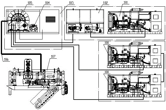
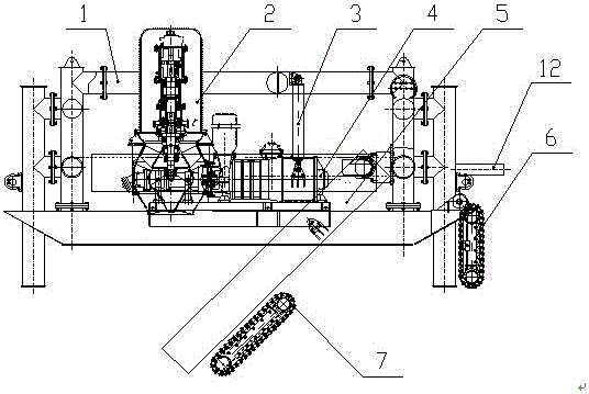
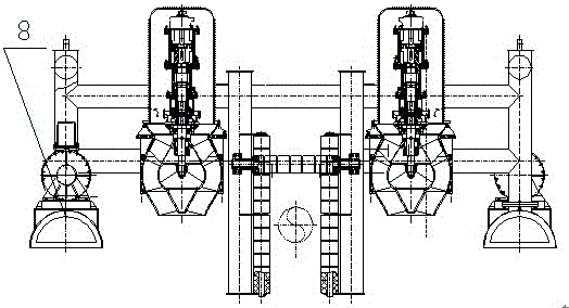
[0034] Refer to attached figure 1 And attached Figure 2-6 , the composition of the submarine pipeline trenching machine of the present invention: pump power unit 100, high-pressure water power unit 101, high-pressure water generating unit 102, control unit 103, umbilical cord winch hydraulic station 104, umbilical cord winch 105, umbilical cord 107, trenching machine body 107. Frame 1, axial flow pump 2, lifting hydraulic cylinder 3, centrifugal pump 4, soil breaking plow 5, upper cutting chain 6, lower cutting chain 7, sliding shoe 8, rear tube protector 9, front tube protector 10, culvert Road cover 11, high-pressure water jet 12.

[0035] Among them, many of the above-mentioned components include two left and right parts, which are as follows: left and right sliding boots, left soil breaking plow, right soil breaking plow, left centrifugal pump, right centrifugal pump, left axial flow pump, right axial flow pump, left high pressure water jet device, right high pressure ...

Embodiment 2

[0040] Refer to attached figure 1 And attached Figure 8-10 , Another kind of scheme of the present invention form is: on the basis of embodiment 1, remove lifting hydraulic cylinder 3, break ground plow 5, upper floor cutting chain 6, lower floor cutting chain 7. Increase the dredging pump 13, and lengthen the front tube protector 10 and the rear tube protector 9 downwards, connect the outlets of the two centrifugal pumps 4 to the left and right conduits of the front tube protector 10, and the left and right conduits of the front tube protector 10 become Nozzle mounting wall. In addition, the suction port of the dredging pump is connected to the left and right conduits of the rear pipe protector 9, and it is used as the suction pipe of the dredging pump 13. In this form, the soil below the pipeline is cut under the action of the pressure water generated by the centrifugal pump 4, and the large flow of water generated by the axial flow pump 2 further sprays it to promote its...

Embodiment 3

[0042] Refer to attached figure 1 And attached Figure 11-13 Another solution of the present invention is: on the basis of embodiment 2, a longer cutting chain 14 is installed on the vertical standpipe of the front tube protector 10, and at the same time, the high-pressure water jet 12 in the inward vertical direction, the The injector nozzles 12 are evenly distributed between themselves and the outlet of the centrifugal pump 4 . At this moment, the dredging pump 13 can be removed.

[0043] The present invention is preparing 4 tool kits for the trencher, namely the axial flow pump 2, the centrifugal pump 4, the high-pressure water ejector 12, the dredging pump 13, and the cutting chain 14. According to different soil strengths, different combinations can be used, so that trenching operations can be effectively implemented, and at the same time, it has better economic benefits.


PUM


Abstract

The invention discloses a submarine pipeline trencher and a trenching method thereof. The submarine pipeline trencher comprises a trencher body connected with an umbilical winch through an umbilical cable, wherein the trencher body comprises a machine rack, left and right centrifugal pumps symmetrically arranged on the left and right sides of the machine rack, left and right ground breaking ploughs symmetrically arranged in the middle of the machine rack. The bottoms of the left and right sides of the machine rack are arranged on left and right sliding shoes, the left centrifugal pump is connected with the left ground breaking plough, and the right centrifugal pump is connected with the right ground breaking plough. The left and right ground breaking ploughs are provided with lifting device capable of enabling the ground breaking ploughs to be lifted. Left and right axial flow pumps are respectively arranged at the positions close to the rear portion inside the machine rack. Soil division, breaking and liquefaction are performed through a duct inner cutting chain, high-pressure water and medium-pressure water to enable the soil liquefaction degree to be improved and enable soil to be easily carried away. The submarine pipeline trencher adapts to construction of various soils, especially to hard soil. A duct cover can enable the sediment back-silting and solidification speed to be reduced, quick reduction of mud concentration in the duct is facilitated, and meanwhile pump abrasion is reduced.

Description

technical field [0001] The invention relates to marine engineering machinery, in particular to a submarine pipeline trenching machine and a trenching method thereof. Background technique [0002] At present, most of the subsea pipeline trenchers at home and abroad are double-acting forming trenchers, that is, the method of liquefying or crushing the soil once and conveying it twice. For complex seabed geological conditions, only one method of soil liquefaction or crushing cannot effectively liquefy or crush various types of soil, and therefore cannot effectively realize soil transportation. In addition, the outlets of the conveying devices of trenching machines at home and abroad are all open, and the discharged sediment is easy to return to the entrance of the liquefaction device. The sediment at the inlet increases the wear and tear on the liquefaction device and reduces the service life of the liquefaction device. [0003] In view of this, in view of the above problems,...

Claims


Application Information

Patent Timeline
Patent Type & Authority Patents(China)
IPC IPC(8): E02F5/02
Inventor 贾芳民高天宝姜俊荣于志鑫刘龙湘李强李丽冯波刘勇
Owner CHINA PETROLEUM & CHEM CORP
Why Eureka
Try Eureka