Fuel vapor liquefaction recovery device and fuel evaporation emission system thereof

A recovery device and fuel vapor technology, applied in the charging system, condensed fuel collection/return, combustion air/combustion-air treatment, etc., can solve the problems of reducing the residual amount of carbon powder, complicated operation and high cost, and achieve effective reduction. Volume, reduce part cost, increase the effect of liquefaction

Active Publication Date: 2020-06-26
DONGFENG MOTOR CORP HUBEI +1
View PDF6 Cites 0 Cited by
  • Summary
  • Abstract
  • Description
  • Claims
  • Application Information

AI Technical Summary

Problems solved by technology

1. Under the condition that the total desorption volume is 120 to 60 times the effective volume of the carbon powder in the carbon tank, it is necessary to fill the carbon tank with special low-permeability carbon powder or add carbon rods (the purpose is to reduce the residual HC in the carbon powder amount), so the cost of the carbon tank will increase by more than 100 yuan
2. Under the condition that the total desorption volume is less than 60 times the effective volume of the carbon powder in the carbon tank, the fuel evaporation control system usually adopts a scheme similar to that of PHEV models, and uses the fuel tank isolation valve to divide the fuel evaporation control system into two parts, so that The leakage detection device of the fuel evaporation control system adopts the DMTL device, which will cause the cost of the entire fuel evaporation control system to increase by more than 500 yuan
However, the negative pressure pump used in this patent is an electrical component, which is costly and has potential safety risks; it is also necessary to add a control valve to start it when refueling, which has high energy consumption and complicated operation

Method used


Image

  • Fuel vapor liquefaction recovery device and fuel evaporation emission system thereof
  • Fuel vapor liquefaction recovery device and fuel evaporation emission system thereof
  • Fuel vapor liquefaction recovery device and fuel evaporation emission system thereof

Examples


Embodiment Construction

[0046] The present invention will be further described in detail below in conjunction with the accompanying drawings and specific embodiments.

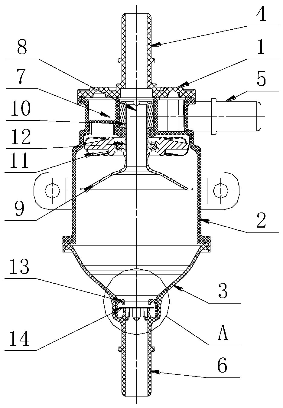
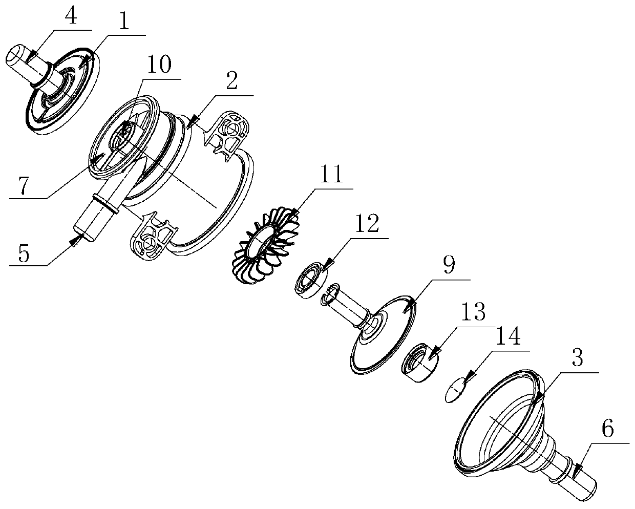
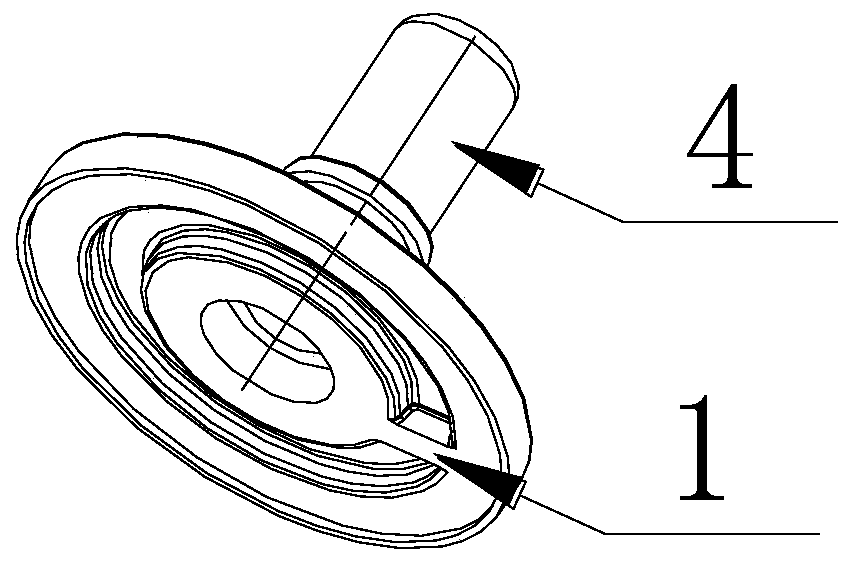
[0047] Such as Figure 1-2 As shown, the present invention provides a fuel vapor liquefaction recovery device, which includes an upper end cover 1, a housing 2, and a lower end cover 3 connected sequentially from top to bottom to form a sealed cavity, and the upper end cover 1, housing 2, and lower end cover 3 are respectively A first pipe joint 4, a second pipe joint 5, and a third pipe joint 6 are provided; an annular self-rotating separation chamber 7 corresponding to the second pipe joint 5 is provided in the housing 2, and the self-rotating separation chamber The inner edge of 7 surrounds and forms a hollow part 8 that penetrates up and down. The upper end of the hollow part 8 communicates with the first pipe joint 4. The casing 2 is provided with an impeller assembly for centrifugal separation and the centrifugally processed Th...


PUM


Abstract

The invention discloses a fuel vapor liquefaction recovery device and a fuel evaporation emission system thereof. The fuel vapor liquefaction recovery device comprises upper end cover, a shell, and alower end cover which are connected in order to form a sealed cavity from top to bottom; the upper end cover, the shell and the lower end cover are respectively provided with a first pipe joint, a second pipe joint and a third pipe joint; an annular self-rotating separation chamber correspondingly communicating with the second pipe joint is provided in the shell; the inner edge of the self-rotating separation chamber is surrounded to form a hollow part penetrating up and down; the upper end of the hollow part communicates with the first pipe joint; the shell is provided with an impeller assembly and a separation guide cover below the self-rotating separation chamber; and the lower end cover is provided with a one-way valve assembly that circulates only in the direction of the third pipe joint. According to the fuel vapor liquefaction recovery device provided by the invention, the kinetic energy formed by high-speed fuel vapor generated during refueling is utilized, and through the self-rotation of the airflow and the centrifugal force separation of blades, tiny droplets are gathered to be liquefied and returned to a fuel tank assembly.

Description

technical field [0001] The invention relates to evaporative emission of vehicle fuel, in particular to a fuel vapor liquefaction recovery device and a fuel evaporative emission system thereof. Background technique [0002] Gasoline used in automobiles is extremely volatile, and direct discharge into the atmosphere will cause air pollution. China has already begun to implement the National VI motor vehicle emission regulations at this stage. The type VII test stipulated in the regulations is to test the emission of gasoline vapor when the vehicle is refueled, and the emission of HC is required to be ≤0.05g / L. The current mature solution is to use a larger volume of activated carbon to absorb the gasoline vapor generated when refueling. The emission of gasoline vapor is directly proportional to the effective volume of carbon powder in the carbon tank. If the volume of carbon powder in the carbon tank is large, the emission of gasoline vapor volatilized from the carbon tank wi...

Claims


Application Information

Patent Timeline
Patent Type & Authority Applications(China)
IPC IPC(8): F02M33/02F02M33/08
CPCF02M33/025F02M33/08
Inventor 黄运忠吴晓飞杨依占祺郭蓉贞
Owner DONGFENG MOTOR CORP HUBEI
Why Eureka
Try Eureka