Internal combustion engine economizer

A technology of fuel economizer and internal combustion engine, which is applied in the direction of internal combustion piston engine, combustion engine, machine/engine, etc. It can solve the problems of energy saving and emission reduction of internal combustion engine, complex and uncompact structure, low ozone production rate, etc., and achieve high efficiency Superior, simplified device complexity, large ozone effect

Inactive Publication Date: 2014-05-14
QINGDAO SHENGTENG ENERGY SAVING TECH
View PDF7 Cites 6 Cited by
  • Summary
  • Abstract
  • Description
  • Claims
  • Application Information

AI Technical Summary

Problems solved by technology

[0002] Energy saving and emission reduction has become a global concern. As a large type of mechanical equipment that consumes energy, the internal combustion engine has achieved undoubted results, but the energy consumption and environmental pollution it brings are also problems that need to be solved urgently.
There are many ways to save energy for internal combustion engines. Fuel economizer is one of the most effective ways. The principle of increasing the amount of oxygen to fully burn oil and gas to reduce energy consumption is the most widely used. However, at present, fuel economizers using this principle are all The heat dissipation performance is poor, the ozone generation rate of the ozone generating device is low, the ozone will dissipate automatically after generation, and cannot directly enter the gas supply system, the structure is complex and not compact, and cannot well meet the needs of energy saving and emission reduction of internal combustion engines

Method used


Image

  • Internal combustion engine economizer
  • Internal combustion engine economizer

Examples


Embodiment Construction

[0018] The present invention will be further described below in conjunction with the accompanying drawings.

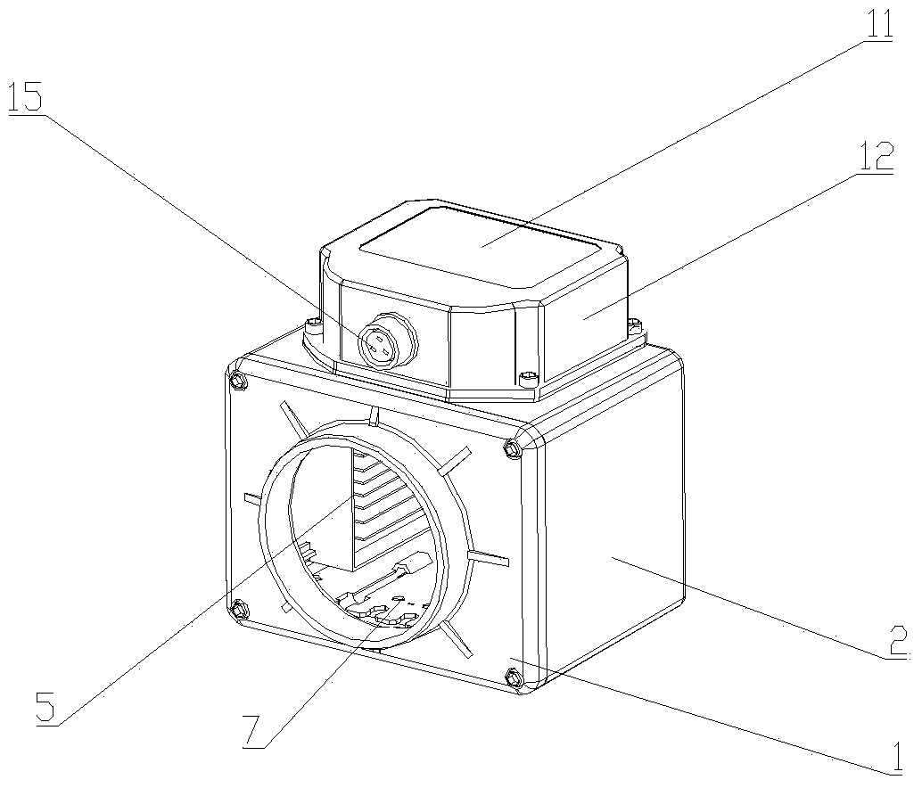
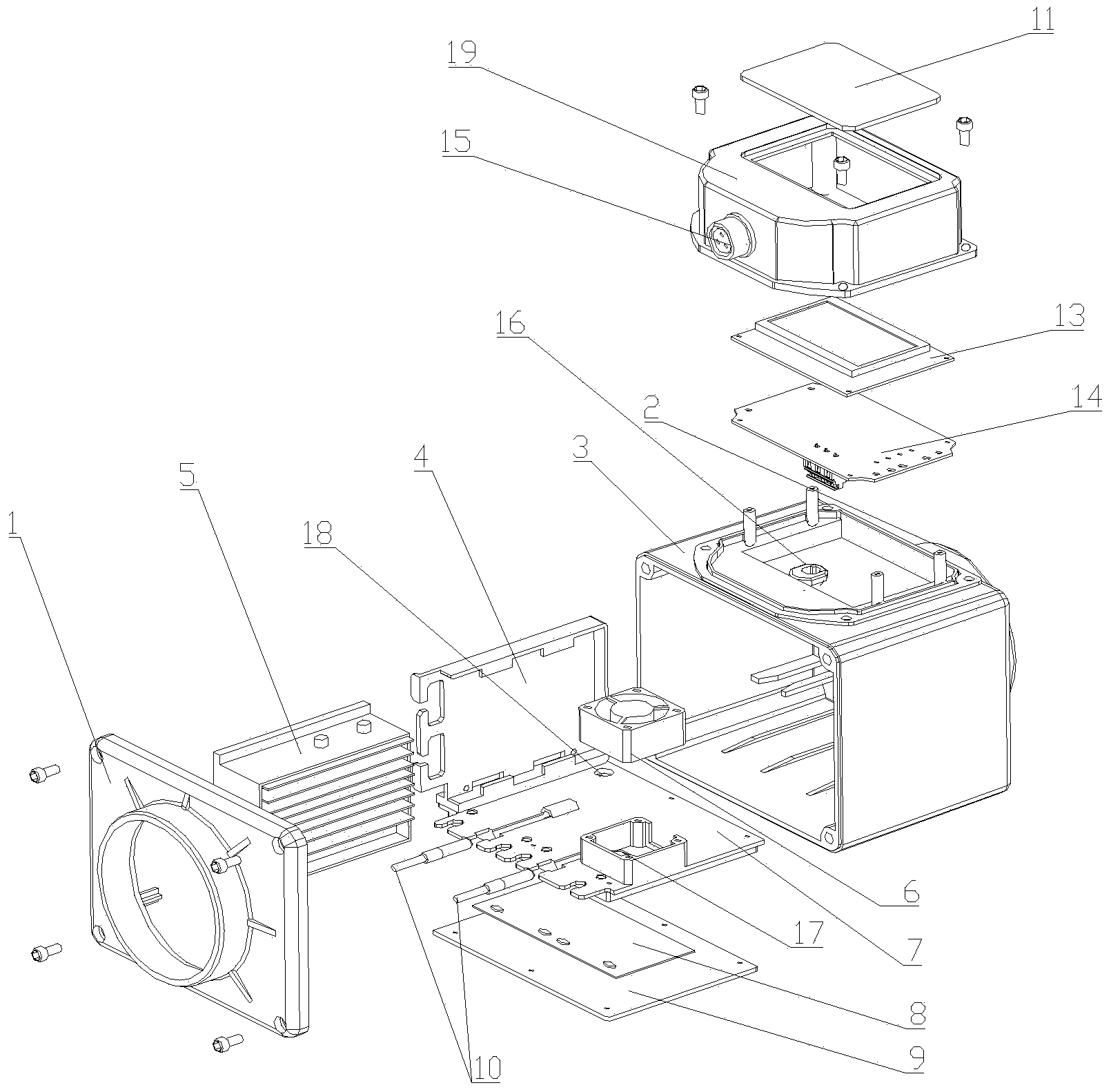
[0019] The internal combustion engine fuel economizer of the present invention comprises a casing 3, an ozone generating device, a power supply 5 and a control device 12, and the two ends of the casing 3 are provided with an air inlet casing cover 1 and an air outlet casing cover 2; Device 12 is arranged on the outer surface of casing 3, and it is electrically connected with ozone generator, power supply 5 respectively and controls ozone generator, power supply 4 work; The inside of casing 3 is provided with ozone generator, and described ozone generator includes Radiating fin 10, anion generating sheet 9 and wind-encapsulating cover 7 are provided with cooling fin 10 at a position close to casing 3, and described air-enclosing cover 7 is fixedly connected with cooling fin 10 to form a sealed space, and anion generating sheet 9 is arranged on Inside the sealed space, t...


PUM


Abstract

The invention aims at providing an internal combustion engine economizer which is superior in heat dissipation performance, high in ozone generation rate, compact and simple in structure and easy to install. The internal combustion engine economizer comprises a housing, an ozone generation device, a power supply and a control device, wherein an air inlet and an air outlet are respectively arranged at two ends of the housing, and the housing is provided with a housing cover. The control device is arranged on the outer side of the housing and respectively connected with the ozone generation device and the power supply electrically. The ozone generation device arranged in the housing comprises cooling fins and a trapped air cover, the cooling fins is arranged at the position close to the housing, the trapped air cover and the cooling fins are fixedly connected to form a sealed space, a negative ion generating piece is arranged in the sealed space, one side corner of the trapped air cover is provided with a fan, the trapped air cover under the fan is provided with an air flow inlet, and the trapped air cover is further provided with an air flow outlet. A power supply support is arranged on the side in the trapped air cover. The internal combustion engine economizer is superior in efficiency, high in ozone generation efficiency and simple in structure, the utilization rate is improved obviously, and according good oil saving effect is achieved.

Description

technical field [0001] The invention relates to a gas generating device for an internal combustion engine, in particular to an oil-saving device for the gas of an internal combustion engine. Background technique [0002] Energy saving and emission reduction has become a global concern. As a large type of mechanical equipment that consumes energy, the internal combustion engine has achieved undoubted results, but the energy consumption and environmental pollution it brings are also problems that need to be solved urgently. There are many ways to save energy for internal combustion engines. Fuel economizer is one of the most effective ways. The principle of increasing the amount of oxygen to fully burn oil and gas to reduce energy consumption is the most widely used. However, at present, fuel economizers using this principle are all The heat dissipation performance is poor, the ozone generation rate of the ozone generating device is low, the ozone will dissipate automatically ...

Claims


Application Information

Patent Timeline
Patent Type & Authority Applications(China)
IPC IPC(8): F02M25/12
CPCY02T10/12
Inventor 徐杰刘洪梅赵洪源岳鹏飞
Owner QINGDAO SHENGTENG ENERGY SAVING TECH
Why Eureka
Try Eureka