Optical fiber-type tension fence alarm device

An alarm device, optical fiber technology, applied in the direction of alarm, anti-theft alarm, by measuring the change force of the optical property of the material when it is stressed, can solve the problem of video monitoring device, leaking cable device, vibrating cable device, Electronic fence, susceptible to electromagnetic interference, short service life and other problems, to achieve good anti-electromagnetic interference ability, flexible use, low investment cost effect

Inactive Publication Date: 2014-05-14
XIAN JINHE OPTICAL TECH
View PDF0 Cites 8 Cited by
  • Summary
  • Abstract
  • Description
  • Claims
  • Application Information

AI Technical Summary

Problems solved by technology

At present, there are many types of monitoring devices used for this purpose on the market, including infrared radiation devices placed on the fence, video monitoring devices, leakage cable devices, vibration cable devices, electronic fences, power grids, fiber optic interferometry vibration monitoring devices, etc. etc. have also been applied in practice, but due to the limitations of technology and cost, the existing devices still have many deficiencies, such as being susceptible to electromagnetic interference, short service life, high maintenance cost, high false alarm rate, and leakage. Issues such as rate rises
The market still urgently needs a low-cost and effective perimeter security system, and existing devices cannot meet this requirement

Method used


Image

  • Optical fiber-type tension fence alarm device
  • Optical fiber-type tension fence alarm device
  • Optical fiber-type tension fence alarm device

Examples


Embodiment 1

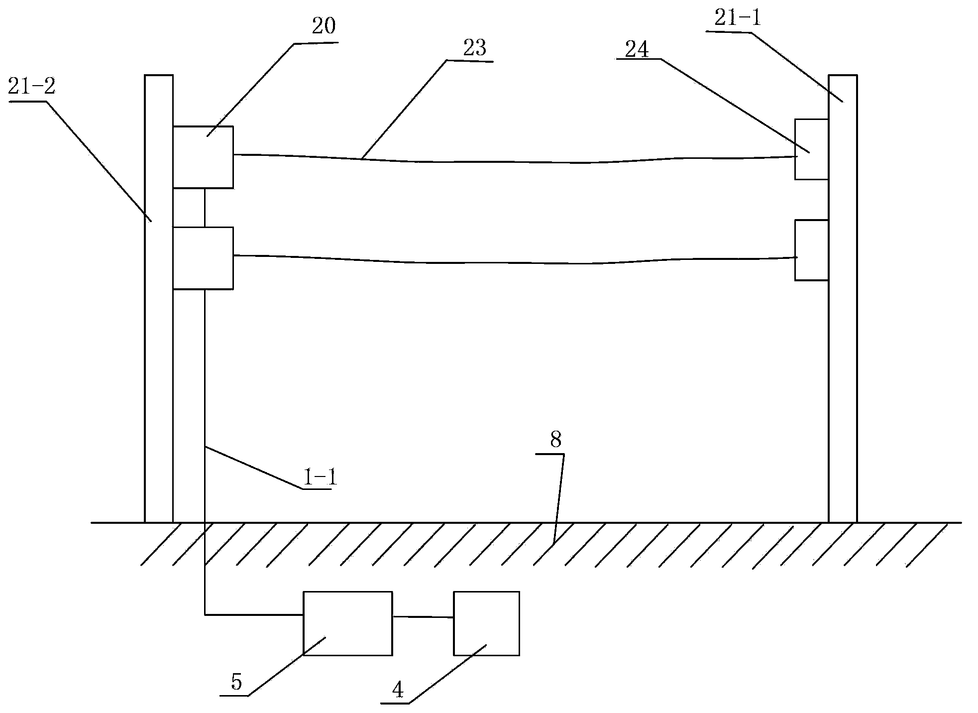
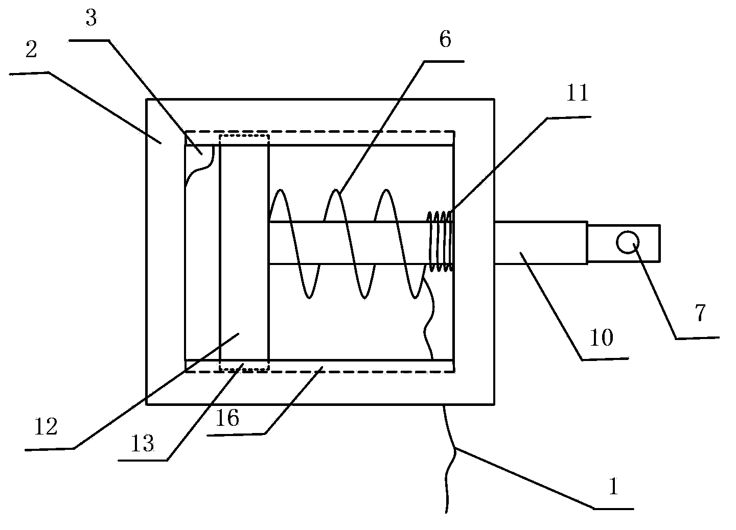
[0039] Such as Figure 1 to Figure 4 As shown, an optical fiber type tension fence alarm device includes a plurality of flexible rods 23, one end of the flexible rod 23 is connected to the column one 21-1 through a fixing part 24, and the other end of the flexible rod 23 is connected to an optical fiber force measuring device 20, the optical fiber force measuring device 20 is installed on the second column 21-2, the first column 21-1 and the second column 21-2 are installed on the base surface 8, and the optical fiber force measuring device 20 includes a housing 2. The moving rod 10 and the optical fiber bending sensing unit 6 arranged in the housing 2, the housing 2 is fixedly connected with the column 2 21-2, the housing 2 is provided with a top cover 3, the housing 2 2 is provided with an opening slidingly fitted with the moving rod 10, one end of the moving rod 10 protrudes into the housing 2 from the opening and is connected with the slide plate 12 arranged in the housing...

Embodiment 2

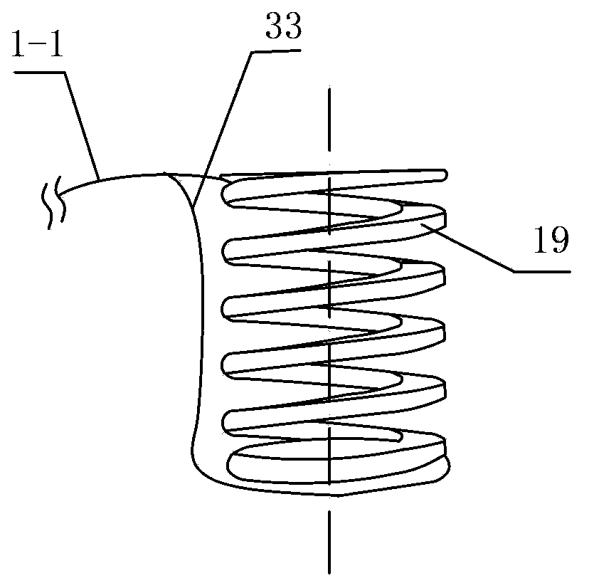
[0048] Such as Figure 5 As shown, the difference between this embodiment and Embodiment 1 is that the curved support contained in the optical fiber bending sensing unit 6 is a spring 38, and a plurality of deformed teeth 1 4-1 and a plurality of deformed teeth 2 4-2 correspond It is arranged between two adjacent coils of spring wire in the spring 38, and the first deformed tooth 4-1 and the second deformed tooth 4-2 are arranged alternately. In this embodiment, the structures, connections and working principles of other parts are the same as those in Embodiment 1.

Embodiment 3

[0050] Such as Image 6 with 7 As shown, the difference between this embodiment and Embodiment 1 is that the curved bracket contained in the optical fiber bending sensing unit 6 is a corrugated tube 40, and the deformed teeth 1 4-1 and deformed teeth 2 4-2 are correspondingly arranged on the corrugated On the two opposite sides of the recess on the tube wall 42 of the tube 40, the first deformed teeth 4-1 and the second deformed teeth 4-2 are arranged alternately. In this embodiment, the structures, connections and working principles of other parts are the same as those in Embodiment 1.


PUM


Abstract

The invention discloses an optical fiber-type tension fence alarm device. The optical fiber-type tension fence alarm device comprises a plurality of flexible bars; one end of each flexible rod is connected with a veridical column 1; the other end of each flexible rod is connected with an optical fiber force measuring device; each optical fiber force measuring device comprises a shell, a movable rod and an optical fiber bending sensor unit; the shell is connected with a veridical column 2; one end of the movable rod extends into the shell and is connected with a sliding plate arranged inside the shell; the other end of the movable rod is arranged outside the shell and is connected with a corresponding flexible rod; the optical fiber bending sensor unit sleeves the movable rod and includes a curved-line-shaped support, a plurality of deformation teeth 1 and a plurality of deformation teeth 2 which are continuously distributed at two opposite sides of the curved-line-shaped support, and a signal optical fiber which is clamped between the deformation teeth 1 and the deformation teeth 2; the signal optical fibers is connected with a test unit; and the test unit is connected with an alarm unit. The optical fiber-type tension fence alarm device of the invention has the advantages of reasonable design, convenient manufacture, low cost, flexible use, high sensitivity, wide dynamic monitoring range and high practical value.

Description

technical field [0001] The invention relates to a safety protection device, in particular to an optical fiber type tension fence alarm device for perimeter protection and alarm. Background technique [0002] Perimeter security devices and intrusion alarm systems are required in many residential quarters, schools, factories, prisons, airports and other occasions. At present, there are many types of monitoring devices used for this purpose on the market, including infrared radiation devices placed on the fence, video monitoring devices, leakage cable devices, vibration cable devices, electronic fences, power grids, fiber optic interferometry vibration monitoring devices, etc. etc. have also been applied in practice, but due to the limitations of technology and cost, the existing devices still have many deficiencies, such as being susceptible to electromagnetic interference, short service life, high maintenance cost, high false alarm rate, and leakage. Issues such as rate incr...

Claims


Application Information

Patent Timeline
Patent Type & Authority Applications(China)
IPC IPC(8): G08B13/186G01L1/24
Inventor 杜兵
Owner XIAN JINHE OPTICAL TECH
Why Eureka
Try Eureka