Heating system for centralized lubrication pipeline and usage method

A heating system and centralized lubrication technology, applied in the direction of lubricating parts, engine lubrication, engine components, etc., can solve the problems of scattered spatial layout of centralized lubrication pipelines, increased oil procurement costs, and blocked lubrication pipelines. Uniform effect, low cost, energy saving effect

Active Publication Date: 2014-05-21
CRRC WIND POWER(SHANDONG) CO LTD
View PDF7 Cites 1 Cited by
  • Summary
  • Abstract
  • Description
  • Claims
  • Application Information

AI Technical Summary

Problems solved by technology

[0003] The pipelines of the centralized lubrication system are thin (generally 4mm-6mm) and long, with many branch pipelines, and the power to transport the grease is also dispersed, which is easy to block the lubrication pipeline due to the viscosity of the low-temperature grease
At the same time, the space layout of the centralized lubrication pipeline is scattered, and the environment of each branch pipeline is different, so it is difficult to uniformly heat each branch pipeline at the same time, and the selection of more cold-resistant low-temperature lubricating grease will greatly increase the purchase cost of oil products

Method used


Image

  • Heating system for centralized lubrication pipeline and usage method
  • Heating system for centralized lubrication pipeline and usage method
  • Heating system for centralized lubrication pipeline and usage method

Examples


Embodiment Construction

[0039] The present invention will be further described below in conjunction with the accompanying drawings and embodiments. It should be noted that the following description is only for explaining the present invention and not limiting its content.

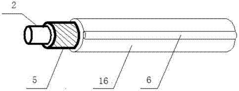
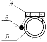
[0040] Such as figure 1 As shown, the present invention is a heating system for lubricating pipelines, which includes: electric heating oil pipe, return line 6, summary terminal block, connecting ring 7, power supply 13, temperature control switch 9, timer 12 , Contactor 10, circuit breaker 14, external resistance wire 15.

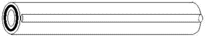
[0041] The structure of the electric heating oil pipe is similar to the shielded cable style, and the inner heating net is tightly wrapped on the outer wall of the inner oil pipe 2, and the internal lubricating pipeline is electrically heated by an external power supply, and the electric heating net 5 is wrapped with an insulating insulation layer.

[0042] The power source 13 is AC or DC.

[0043] The retur...


PUM


Abstract

The invention discloses a heating system for a centralized lubrication pipeline and a usage method. The system comprises a terminal strip, electric heating nets, return lines, connecting rings, external heating wires, a temperature control switch, a contactor, a timer, a heating power supply and a circuit breaker, wherein the electric heating nets of all oil pipelines are connected in series sequentially through the terminal strip; the electric heating nets are arranged inside the oil pipelines; the return lines are parallel with and insulated from the electric heating nets; the connecting rings are arranged at two ends of each oil pipeline; the temperature control switch is used for controlling connection of the power supply; the contactor is controlled to be connected with the power supply; the timer is responsible for setting of cycles and time; and the circuit breaker plays a role in protection. The electric heating nets, with which the pipelines are sleeved, are electrically connected in series, and the power supply is switched on under the control of the temperature control switch so as to heat the whole pipeline. The method is even and synchronous in pipeline heating effect, one power supply can drive heating of all the branch pipelines, the heating efficiency is high, and the cost is low; and the heating power supply can be adjusted according to specific conditions of the pipelines after laying, so that the method can meet requirements under different conditions more flexibly as well as meet requirements of pipeline transformation in the future.

Description

technical field [0001] The invention relates to a heating system, in particular to a centralized lubrication pipeline heating system and a use method. Background technique [0002] In the case of low temperature, low-temperature lubricating grease can be used for the lubrication of equipment. Although low-temperature lubricating grease can guarantee its performance at extremely low temperatures, it will also become more viscous and even agglomerate due to lower temperature. Under such a low temperature condition, the resistance of the lubricating grease increases when it is transported through a long path and small-diameter lubricating pipeline, and it is very easy to be blocked, so that the components cannot be effectively lubricated. [0003] The pipelines of the centralized lubrication system are thin (generally 4mm-6mm) and long, with many branch pipelines, and the power to transport the grease is also dispersed, which is easy to block the lubrication pipeline due to the...

Claims


Application Information

Patent Timeline
Patent Type & Authority Applications(China)
IPC IPC(8): F16N39/04F16N29/04
Inventor 张雷王鹏吴得宗
Owner CRRC WIND POWER(SHANDONG) CO LTD
Why Eureka
Try Eureka